Fontana Commercial Sensor Faucets™ | Architectural and Engineering Resource
Fontana FS-354AQ-DP Antique Commercial Automatic Sensor Faucet:
Service, Maintenance, and Component-Access Diagram
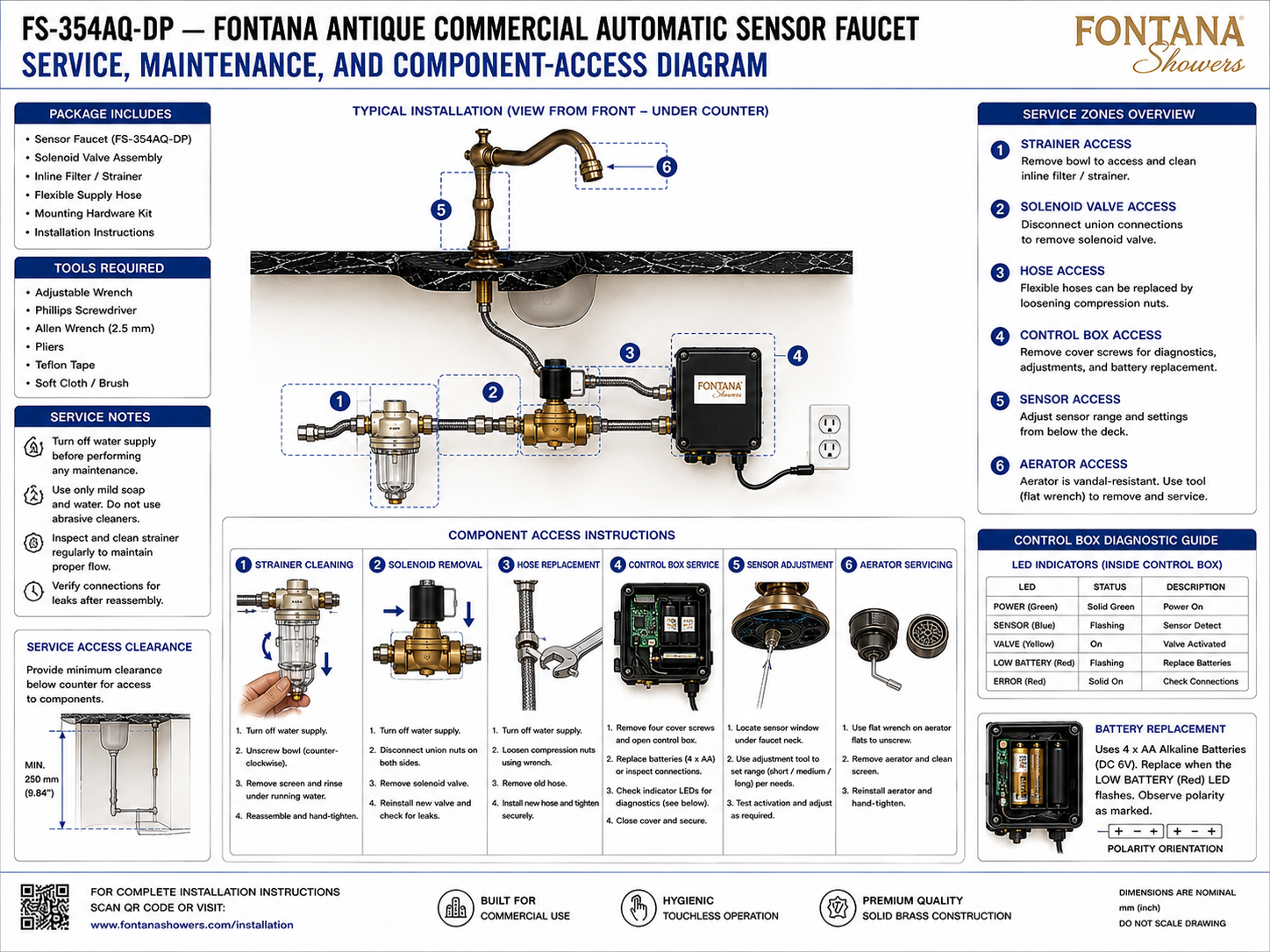
This service, maintenance and component-access resource supports facility
managers, maintenance personnel, plumbing contractors, installers and
specifiers responsible for the Fontana FS-354AQ-DP commercial automatic
sensor faucet. The diagram identifies the principal service zones for the
inline filter / strainer, solenoid valve, flexible hoses, electronic
control box, sensor and vandal-resistant aerator. It also establishes
the minimum under-counter service clearance, diagnostic indicators,
battery-replacement access and basic component-removal procedures needed
for routine inspection and maintenance.
FS-354AQ-DP Serviceable Component Architecture
The FS-354AQ-DP installation provides separate service points
for the faucet's hydraulic and electronic components. Routine
maintenance can include cleaning the inline strainer, removing
or replacing the solenoid valve, replacing flexible hoses,
accessing the electronic control box, adjusting the sensor,
servicing the aerator and replacing the four-AA battery set.
The under-counter installation should remain accessible so these
tasks can be completed without disturbing the countertop or basin.
-
Model:
FS-354AQ-DP
-
Fixture type:
Commercial automatic sensor faucet
-
Service Zone 1:
Inline filter / strainer access
-
Service Zone 2:
Solenoid-valve access
-
Service Zone 3:
Flexible-hose access
-
Service Zone 4:
Electronic control-box access
-
Service Zone 5:
Sensor adjustment access
-
Service Zone 6:
Aerator servicing access
-
Minimum under-counter clearance:
250 mm (9.84 in)
-
Battery configuration:
4 × AA alkaline batteries, DC 6V
-
Low-battery indication:
Red LED flashes
-
Strainer maintenance:
Remove bowl and clean screen
-
Solenoid servicing:
Disconnect union connections for removal
-
Sensor adjustment:
Accessible from below the deck
-
Aerator:
Vandal-resistant, removable with service tool
Required Service & Component-Access Drawing Package
The service drawing should identify each component that requires
inspection, cleaning, adjustment or replacement and establish a
clear route for technician access. The inline strainer, solenoid
valve, flexible hoses and electronic control box should remain
reachable below the counter, while the sensor and aerator require
dedicated access at the faucet assembly. A minimum clear working
zone should be preserved in front of the under-counter components
so maintenance can be performed without dismantling surrounding
casework.
Service, Maintenance & Component-Access Diagram
Shows the complete service architecture for the
FS-354AQ-DP, identifying six principal access zones
for the strainer, solenoid valve, hoses, control box,
sensor and aerator together with the minimum
under-counter service clearance.
1. Strainer Access
The inline filter / strainer is serviced from below
the counter. Shut off the water supply, unscrew the
filter bowl counterclockwise, remove the internal screen
and rinse the screen under running water before
reassembly.
2. Solenoid-Valve Access
The solenoid valve can be removed after the water supply
has been isolated and the union connections on both sides
have been disconnected. After servicing or replacement,
reinstall the valve and inspect the completed joints for leaks.
3. Flexible-Hose Access
The flexible water hoses can be removed by loosening
the compression nuts with the appropriate wrench.
Replacement hoses should be installed securely and
checked for proper routing and leak-free connections
before the faucet is returned to service.
4. Control-Box Service
The electronic control box is accessed by removing the
four cover screws and opening the enclosure. Internal
access supports diagnostics, LED inspection, adjustment
and battery replacement before the cover is secured again.
5. Sensor Adjustment
The sensor-adjustment point is accessible from below
the faucet neck. Use the designated adjustment tool to
set the sensor response as required and test activation
after completing the adjustment.
6. Aerator Servicing
The faucet incorporates a vandal-resistant aerator.
Use the appropriate flat service wrench to loosen the
aerator, remove and clean the screen, and reinstall
the assembly hand-tight after maintenance.
Battery Replacement
The control system uses four AA alkaline batteries
providing DC 6V power. Replace the batteries when
the red LOW BATTERY indicator flashes and observe
the polarity markings shown inside the battery compartment.
Minimum Service Clearance
The supplied drawing identifies a minimum 250 mm
(9.84 in) clear zone below the countertop for access
to the strainer, solenoid, hoses and electronic
control components.
Engineering note:
Turn off the water supply before performing hydraulic maintenance
or component removal. Maintain the specified under-counter access
zone, use appropriate tools, inspect connections after reassembly
and confirm that all serviced components are secure and leak-free
before returning the faucet to normal operation.
Service & Maintenance Coordination Considerations
Water Isolation
Turn off the faucet water supply before removing the
strainer, solenoid valve, flexible hoses or other
wetted components.
Strainer Cleaning
Inspect and clean the inline strainer periodically
to maintain proper flow and reduce debris entering
the solenoid-valve assembly.
Leak Inspection
After reassembling plumbing components, inspect
union fittings, hose connections, filter joints
and solenoid connections for leakage before
returning the system to service.
Control-Box Access
Keep the electronic control enclosure accessible
so diagnostic indicators, battery components and
internal connections can be inspected without
removing surrounding fixtures.
Surface Cleaning
Use mild soap and water for routine faucet cleaning
and avoid abrasive cleaners that could damage the
antique finish or exposed fixture surfaces.
Service Clearance
Maintain at least 250 mm (9.84 in) of clear
working space below the counter so serviceable
components can be reached for inspection,
cleaning and replacement.
Service Zones & Component Functions
Control-Box Diagnostics & Maintenance Requirements
-
POWER – Green LED
A solid green POWER indicator identifies the control
system as powered on.
-
SENSOR – Blue LED
A flashing blue SENSOR indicator identifies sensor
detection activity.
-
VALVE – Yellow LED
An illuminated yellow VALVE indicator identifies
the solenoid valve as activated.
-
LOW BATTERY – Red LED
A flashing red LOW BATTERY indicator signals that
the four AA alkaline batteries should be replaced.
-
ERROR – Red LED
A solid red ERROR indicator directs the service
technician to inspect system connections.
-
Battery Replacement
The control system uses four AA alkaline batteries
providing DC 6V. Replace the battery set when the
red low-battery indicator flashes and observe the
indicated polarity orientation.
-
Recommended Service Tools
The supplied drawing identifies an adjustable wrench,
Phillips screwdriver, 2.5 mm Allen wrench, pliers,
Teflon tape and a soft cloth or brush for typical
maintenance work.
-
Post-Service Verification
After maintenance, restore the water supply, inspect
reassembled connections for leakage and confirm
sensor activation, solenoid operation and normal
water delivery.
Project verification:
The service, maintenance and component-access diagram is a
maintenance coordination resource and should not be scaled.
Before servicing the FS-354AQ-DP, isolate the water supply as
required and verify access to the inline strainer, solenoid valve,
flexible hoses, electronic control box, sensor and aerator.
Maintain the indicated 250 mm (9.84 in) minimum under-counter
service clearance, use appropriate service tools, observe battery
polarity, inspect diagnostic indicators and check all reassembled
connections for leakage. After maintenance, confirm sensor detection,
solenoid actuation, water flow and automatic faucet operation before
returning the fixture to service.
|
|
|