Fontana Touchless Faucets™ | Architectural and Engineering Resource
Fontana MotionWave™ Line Brushed Gold Touchless Bathroom Faucet:
Installation Drawings
This installation drawing resource supports architects, plumbing engineers,
interior designers, contractors, installers and facility managers coordinating
the Fontana MotionWave™ wall-mounted touchless faucet within commercial
washrooms. The drawing package communicates the faucet’s relationship to the
finished wall, concealed mounting assembly, lavatory basin, sensor cable,
water connection and required maintenance access.
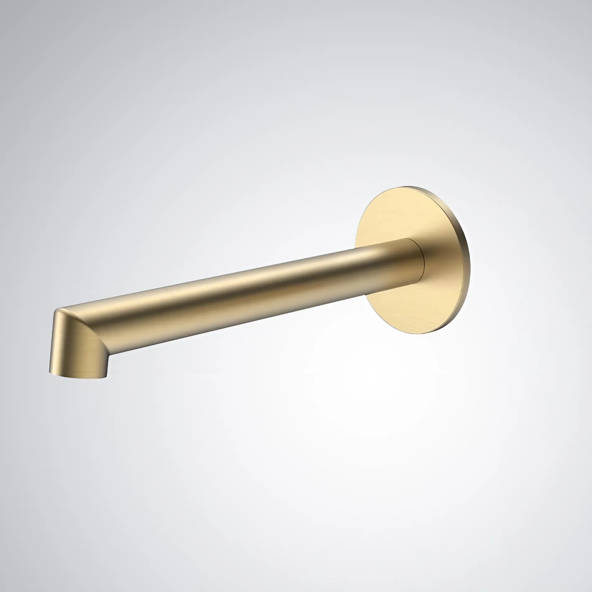
Fontana MotionWave™ Line Brushed Gold Touchless Wall-Mounted Faucet
The Fontana MotionWave™ FS7035BG is a wall-mounted touchless bathroom
faucet constructed from lead-free brass with a brushed gold finish.
Its infrared sensor, ceramic valve and concealed wall connection provide
hands-free operation with a clean architectural appearance.
- Model: FS7035BG
- Installation: Wall mounted
- Material: Lead-free brass
- Finish: Brushed Gold
- Valve: Ceramic valve, included
- Flow rate: 1.2 GPM / 4.5 LPM
- Water connection: 1/2-inch NPT
- Spout reach: 6.93 inches
- Overall projection: 7.87 inches / 200 mm
- Escutcheon diameter: 3.94 inches / 100 mm
- Spout body dimension: 0.87 inch / 22 mm
- Overall height: 2.76 inches
- Minimum operating pressure: 0.05 MPa / 0.5 bar
- Accessibility: ADA compliant
Required Standard Overall Dimension Drawing Package
Each drawing should use a consistent scale, dimension style and product
identification block. Measurements should be referenced from the finished
wall, faucet centerline, outlet centerline and basin datum. Drawings should
also identify the 1/2-inch NPT water connection, sensor cable route,
concealed mounting assembly and required service clearance.
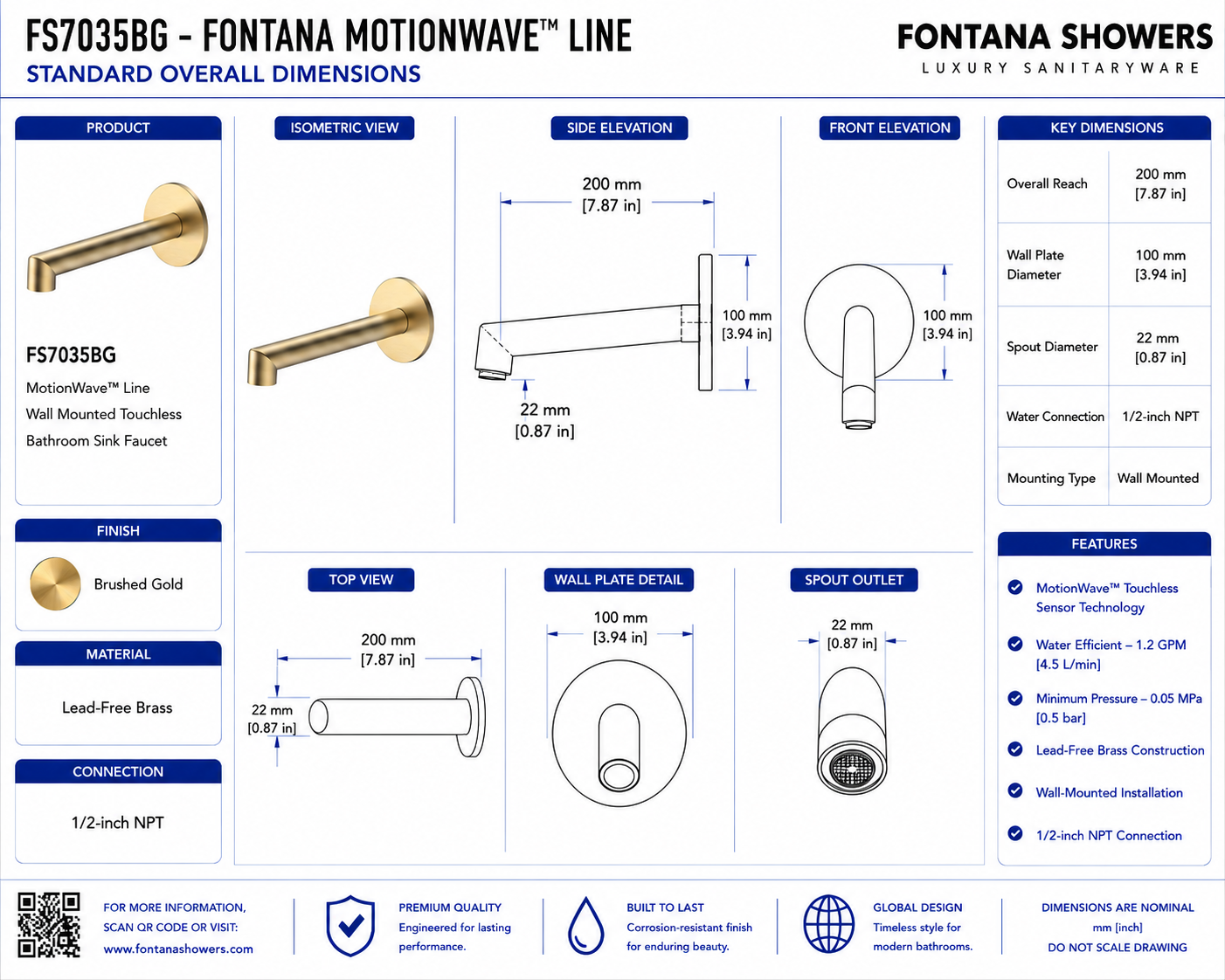
Standard Overall Dimensions
Shows the verified 7.87-inch / 200 mm overall projection,
6.93-inch spout reach, 3.94-inch / 100 mm round escutcheon
diameter, 0.87-inch / 22 mm spout body dimension and
2.76-inch overall height. The 3.94-inch measurement applies
to the wall ring or escutcheon, not the spout projection.
Wall Rough-In Installation Drawing
Defines the concealed water supply, wall opening, blocking,
mounting plate and sensor-cable route before the finished wall
is closed. Rough-in depth must position the escutcheon flush
with the completed wall surface.
Front Elevation
Displays the round 3.94-inch / 100 mm escutcheon, faucet
centerline, outlet position and alignment with the lavatory.
This view helps maintain consistent fixture elevations across
multi-station commercial washrooms.
Side Elevation
Illustrates the 7.87-inch / 200 mm overall projection and
6.93-inch spout reach in relation to the finished wall and basin.
This view supports splash-control, backsplash-clearance and
user-reach evaluation.
Top Plan View
Defines the horizontal faucet centerline and its relationship
to the basin center, rear rim and adjacent accessories. The plan
view helps prevent conflicts with mirrors, soap dispensers and
neighboring fixtures.
Wall Opening and Finished-Surface Clearance
Coordinates the wall penetration with the mounting plate,
concealed connection, sensor cable and 3.94-inch / 100 mm
escutcheon. The ring must fully cover the prepared opening while
seating evenly against the finished surface.
Spout Reach and Basin Water Impact Zone
Identifies the 6.93-inch reach from the wall-mounted assembly
to the outlet and locates the discharge over the basin’s usable
capture area. Correct alignment limits splash onto the rear wall,
countertop and front rim.
Sensor Location and Detection Zone
Identifies the infrared sensor position beneath the outlet and
illustrates the hand-detection field using the approved project
submittal setting. The basin profile and reflective finishes
should be checked during final sensor commissioning.
Engineering note: Do not add estimated product dimensions
to construction documents. Final measurements must be taken from the
approved FontanaShowers specification sheet, installation instructions or
project submittal package before countertop openings and utility locations
are established.
Architectural and MEP Coordination Considerations
Lavatory Alignment
Position the 6.93-inch-reach outlet over the basin’s usable
capture area to control splash and keep water away from the rear
wall, countertop and front rim.
Wall Rough-In
Coordinate the concealed mounting plate, blocking, wall opening
and finished-surface depth so the 3.94-inch / 100 mm escutcheon
seats flush and fully covers the penetration.
Sensor Cable Routing
Route the sensor cable separately from sharp edges, fasteners
and heat sources. Protect the cable through the wall cavity and
preserve access for connection, testing and replacement.
Hydraulic Performance
Confirm at least 0.05 MPa / 0.5 bar operating pressure and test
the regulated 1.2 GPM / 4.5 LPM discharge after the supply line
has been flushed and the faucet commissioned.
Water Connection
Provide an accessible 1/2-inch NPT water connection and service
stop. Confirm thread engagement, flexible-pipe routing and leak-free
operation before closing the service area.
Service Access
Maintain access to the sensor cable, control valve, supply
connection and serviceable components without removing permanent
wall finishes or disturbing the faucet mounting assembly.
FontanaShowers Installation and Specification Resources
FS7035BG Product Page
Product information, technical specifications, finish details and
available resources for the MotionWave™ wall-mounted touchless faucet.
FS7035BG Installation Instructions
Wall-mounting, sensor-cable, flexible-water-pipe and installation
guidance specific to the FS7035BG faucet.
FS7035BG Standard Overall Dimensions
Official specification and dimensional drawing for coordinating
projection, spout reach, escutcheon size and wall installation.
FontanaShowers Installation Hub
Central installation guidance for touchless faucets, bathroom
faucets, automatic dispensers and related commercial fixtures.
Bathroom Fixture BIM Files
BIM and architectural coordination resources for plumbing fixture
planning, design development and project documentation.
Architect and Designer Specifications
Specification support and project documentation resources for
architects, designers, engineers and commercial contractors.
Professional Engineering and Accessibility References
Project verification: Installation drawings are coordination
tools and do not replace approved project submittals. The architect, engineer
and licensed installer should verify final dimensions, wall construction,
mounting support, waterproofing, water connections, sensor-cable routing,
service access, commissioning, accessibility criteria and locally adopted
codes before installation.
|
|
|