Fontana Touchless Faucets™ | Architectural and Engineering Resource
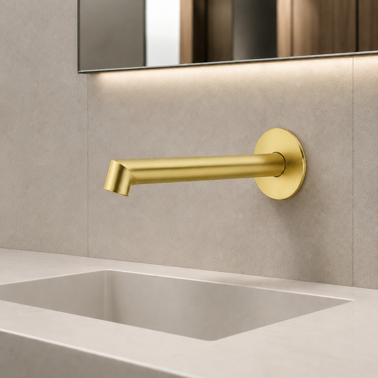
Fontana MotionWave™ Line Brushed Gold Touchless Bathroom Faucet:
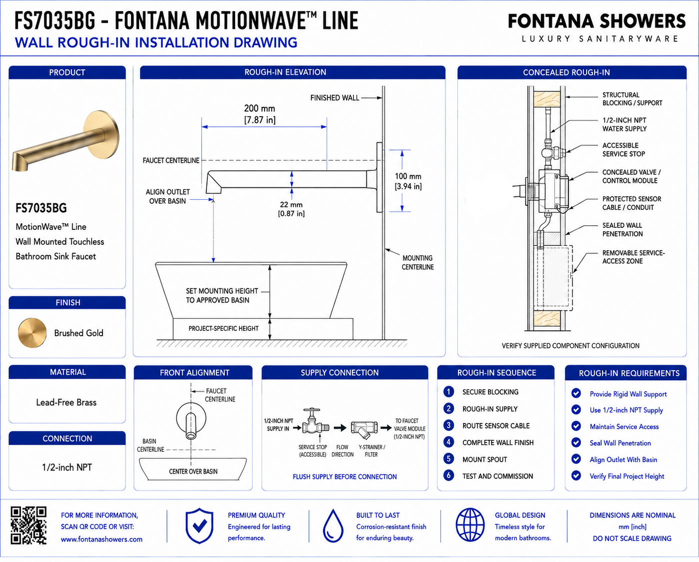
Wall Rough-In Installation Drawing
This wall rough-in installation drawing resource supports architects,
plumbing engineers, electrical engineers, interior designers, wall-system
contractors, installers and facility managers coordinating the Fontana
MotionWave™ Line FS7035BG wall-mounted touchless bathroom faucet within
commercial washrooms. The drawing identifies the spout mounting centerline,
finished-wall relationship, concealed mounting plate, water-supply route,
sensor cable, control box, power arrangement, basin alignment and service
clearances that should be established before wall closure and final installation.
Fontana MotionWave™ Line FS7035BG Touchless Bathroom Faucet
The Fontana FS7035BG is a wall-mounted touchless bathroom faucet
constructed from lead-free brass with a brushed gold finish. The visible
spout and round escutcheon mount at the finished wall while the flexible
water pipe and sensor cable route to the accessible control box below
the lavatory.
- Model: FS7035BG
- Product type: Touchless bathroom faucet
- Installation: Wall mounted
- Operation: Infrared sensor activation
- Material: Lead-free brass
- Finish: Brushed Gold
- Valve: Ceramic valve
- Flow rate: 1.2 GPM / 4.5 LPM
- Water connection: G1/2 / 1/2-inch NPT
- Power: 6V DC using 4 AA batteries or 220V AC control-box option
- Minimum operating pressure: 0.05 MPa / 0.5 bar
- Spout reach: 6.93 inches
- Overall projection: 7.87 inches / 200 mm
- Escutcheon diameter: 3.94 inches / 100 mm
- Application: Commercial and architectural washrooms
Wall Rough-In Installation Drawing Scope
The rough-in drawing should present the complete relationship between the
visible wall-mounted spout, finished wall, concealed mounting assembly,
lavatory basin, flexible water pipe, sensor cable, control box, power source
and service-access area. Reference dimensions should be taken from the
finished wall, faucet centerline, outlet centerline, basin rim and finished
floor. Only verified manufacturer dimensions should be included in final
construction documents.
Complete Wall Rough-In Elevation
Shows the spout at the finished wall and all connected equipment below
the basin. The elevation should identify the mounting plate, wall
penetration, flexible water pipe, sensor cable, control box, power source,
water supply and required maintenance-access zone.
Spout Mounting Centerline
Identifies the faucet centerline in relation to the basin, finished wall
and drain. The outlet should discharge within the basin’s effective
capture area without striking the rim or creating excessive splash.
Wall Penetration
Indicates the verified opening and route required for the flexible water
pipe and sensor cable. The penetration should be coordinated with studs,
blocking, waterproofing, tile joints and concealed building services.
Finished-Wall Depth
Shows the wall substrate, finish build-up and mounting assembly depth
required for the round escutcheon to seat evenly against the completed
wall without leaving gaps or restricting the spout connection.
Faucet Spout Projection
Shows the 7.87-inch / 200 mm overall projection and 6.93-inch spout
reach in relation to the basin rim and drain centerline. Placement should
direct the stream into the usable basin area.
Sensor Detection Zone
Identifies the infrared sensing field below the outlet. The zone should
remain clear of the basin wall, drain fitting, backsplash, soap dispenser
and reflective accessories that could cause false activation.
Concealed Wall-Cavity Envelope
Defines the available cavity depth and width for the mounting plate,
fasteners, flexible water pipe and protected sensor-cable route. The
assembly should not conflict with studs, insulation or other services.
Water-Supply Stub-Out
Shows the required water-supply connection serving the control box.
The stub-out and isolation valve should remain accessible and positioned
to avoid sharp hose bends, tension and interference with the drain.
Isolation Valve Position
Identifies an accessible shutoff valve serving the faucet. The valve
should permit individual fixture isolation for commissioning,
maintenance and component replacement.
Control Box Location
Shows the control box mounted vertically in a dry, accessible location
below the basin. The box should remain within the approved reach of the
sensor cable, flexible outlet hose and incoming water supply.
Control Box Mounting
Identifies the mounting surface, fasteners and upright orientation for
the approximately 5-inch-wide by 4.7-inch-high control box. The cover
must remain removable for battery and valve service.
AC Power-Supply Location
Where 220V AC operation is selected, show the approved adapter and
receptacle in a dry, serviceable location separated from plumbing joints,
potential leakage points and wet cleaning areas.
Battery Box Location
Where 6V DC operation is selected, show the four-AA-battery compartment
within the control box. Locate the unit so its cover and battery case can
be removed without disconnecting the plumbing.
Electrical Receptacle Coordination
If a receptacle is required, coordinate its location with the electrical
drawings and locally adopted requirements. It should not conflict with
the trap, shutoff valve or maintenance-access area.
Sensor Cable Route
Shows the low-voltage cable path from the wall-mounted spout to the
control box. The cable should be protected through the wall and kept
clear of sharp edges, fasteners, heat sources and moving hardware.
Control Valve Orientation
Identifies the G1/2 inlet and outlet on the control box and the intended
direction of water flow. Connections should remain visible and reachable
for testing, cleaning and future component replacement.
Flexible Water-Pipe Route
Shows the concealed pipe from the faucet spout to the control-box outlet.
The pipe should follow a smooth route and should not be twisted, kinked,
stretched or compressed within the wall or cabinet space.
Drain and Supply Separation
Coordinates the control box, supply hose and sensor cable with the
lavatory drain and trap. Electrical components should not rest against
drainage piping or obstruct access to service connections.
Minimum Service Height
Defines the vertical clearance required to remove the control-box cover,
battery case, hose connections and cable connector. This zone should
remain unobstructed after all plumbing is installed.
Minimum Service Depth
Indicates the horizontal clearance needed to inspect and remove the
control box and connected hoses. Equipment should be serviceable through
the normal access opening without removing the basin or wall finish.
Front Access Zone
Shows the clear working area required in front of the control box,
isolation valve and water connections. Cabinet doors or removable panels
should permit servicing without dismantling permanent construction.
Moisture Protection
Shows the control box and electrical connections raised above the lowest
cabinet level where practical. Components should be protected from leaks,
cleaning water, condensation and standing moisture.
Basin Reflection Clearance
Identifies the relationship between the infrared sensor and reflective
basin surfaces. Highly reflective finishes should be reviewed during
commissioning to prevent continuous or unintended activation.
Finished Rough-In Arrangement
Presents the coordinated layout after the wall construction, basin,
plumbing, electrical components and access conditions have been reviewed.
All components should remain organized, labelled and serviceable.
Engineering note: Rough-in dimensions must not be based
on estimated product measurements. Confirm the wall opening, finished-wall
depth, mounting-plate position, flexible water-pipe length, sensor-cable
reach, control-box dimensions, valve orientation and power requirements
from the approved FontanaShowers specification sheet or project submittal
before wall closure.
Required Wall Rough-In Drawing Views
Front Lavatory Elevation
Show the faucet centerline, finished wall, round escutcheon, lavatory
basin, control box, power source, water supply, drain and front
service-access zone.
Side Wall Section
Show the spout projection, wall finish, mounting plate, blocking,
concealed water pipe, sensor cable, basin and available wall-cavity depth.
Wall Opening Elevation
Show the faucet centerline, prepared penetration, mounting-plate holes,
blocking, cable route and minimum coverage provided by the
3.94-inch / 100 mm escutcheon.
Below-Basin Plan View
Show the basin footprint, drain, trap, isolation valve, control box,
power source and all water-hose and sensor-cable routes.
Mounting-Plate Detail
Show the wall substrate, blocking, anchors, mounting screws, concealed
spout sleeve, escutcheon and final finished-wall interface.
Hydraulic Connection Diagram
Show the building supply, isolation valve, control-box inlet, integrated
water-control valve, outlet hose and wall-mounted spout in the correct
direction of flow.
Electrical Connection Diagram
Show the faucet sensor, control box, battery compartment, approved AC
adapter where selected, cable connector and power source.
Sensor Commissioning View
Show the intended hand-detection zone and its relationship to the basin,
soap dispenser and water-stream landing point for final calibration.
Recommended Wall Rough-In Installation Sequence
1. Review Approved Submittals
Confirm the final model, finish, faucet dimensions, power configuration,
control-box arrangement and installation accessories before preparing
the rough-in.
2. Coordinate the Spout Centerline
Position the wall-mounted outlet so the water stream enters the basin
capture area while maintaining suitable clearance above the rim.
3. Review Wall-Cavity Conflicts
Check the faucet location against studs, blocking, insulation, piping,
conduit, waterproofing and other concealed building services.
4. Reserve the Equipment Zone
Establish a dry, accessible area below the basin for the control box,
power components, water connections and cable connector.
5. Install the Water-Supply Stub-Out
Provide an accessible supply and isolation valve that permit direct
connection to the G1/2 control-box inlet without sharply bending or
stretching the hose.
6. Coordinate Electrical Power
Provide the selected 220V AC source or four-AA-battery access in a dry,
serviceable location consistent with the project electrical drawings.
7. Prepare the Wall Opening
Transfer the verified mounting and routing requirements to the wall
layout, then coordinate the penetration with the final finish thickness
and escutcheon coverage.
8. Install Blocking and Mounting Plate
Provide secure backing, anchors and a level mounting plate capable of
maintaining the spout position without movement at the finished wall.
9. Route the Water Pipe and Cable
Keep the flexible water pipe and sensor cable organized, protected and
clear of sharp edges, fasteners, heat sources and tight bends.
10. Verify Service Access
Confirm the control box, battery compartment, power connection, sensor
connector, supply valve and hose connections remain reachable.
11. Flush the Water Supply
Flush the supply piping before connecting the control box so construction
debris does not enter the valve, flexible pipe or faucet outlet.
12. Inspect Before Wall Closure
Complete a rough-in inspection and document concealed connections before
installing permanent board, tile, stone or wall panels.
Architectural and MEP Coordination Considerations
Lavatory Coordination
The outlet should discharge within the basin while the sensor field
remains clear of surfaces that could trigger unintended activation.
Wall Construction Coordination
Studs, blocking, wallboard, tile, stone and finish build-up should support
the faucet without conflicting with the concealed pipe or sensor cable.
Waterproofing Coordination
Seal the wall penetration using materials compatible with the substrate
and finish while allowing the escutcheon to seat flat against the wall.
Plumbing Coordination
Maintain access to the isolation valve, G1/2 connections, control box
and drain while protecting the sensor cable and electrical components
from potential leaks.
Electrical Coordination
Confirm the approved AC or battery configuration, adapter arrangement,
receptacle location and separation between electrical and plumbing
components.
Maintenance Coordination
Provide sufficient access for control-box cover removal, battery
replacement, valve service, connector testing and supply isolation.
Accessibility Coordination
Coordinate the faucet location, sensor activation zone, lavatory height,
knee clearance and clear floor space with applicable accessibility
requirements.
Splash-Control Coordination
Review basin depth, drain position, the 6.93-inch spout reach and
operating pressure so the stream does not produce excessive splash.
Sensor and Hydraulic Commissioning Requirements
Sensor Calibration
After connecting the sensor cable and applying power, keep the detection
area clear while the faucet completes its automatic calibration cycle.
Multiple-Angle Activation Test
Test activation from the front and both sides of the basin to confirm
the faucet responds consistently throughout the intended approach.
False-Trigger Test
Verify that reflective basin surfaces, the soap dispenser, lighting
conditions and nearby fixtures do not trigger unintended flow.
Water-Stream Alignment
Confirm the stream enters the basin’s capture area without striking the
drain directly or contacting a steep surface that could cause splash.
Pressure and Leak Test
Confirm at least 0.05 MPa / 0.5 bar operating pressure, pressurize the
system and inspect all supply, control-box and faucet connections.
Automatic Shut-Off Test
Remove hands from the detection zone and confirm flow stops promptly.
Also verify the safety time-out interrupts extended activation.
Power-Failure Test
Where AC with battery backup is provided, interrupt mains power and
confirm the faucet transfers to battery operation as intended.
Final Functional Test
Complete repeated activation cycles to confirm stable sensor response,
consistent 1.2 GPM flow, prompt shut-off and acceptable splash control.
Wall Rough-In Component Identification
-
Wall-mounted faucet spout:
Visible lead-free-brass component containing the water outlet and
infrared sensor assembly.
-
Infrared sensor:
Detects the user’s hands and sends the activation signal through the
sensor cable to the control box.
-
Round escutcheon:
The 3.94-inch / 100 mm wall ring that covers the mounting plate and
finished-wall penetration.
-
Mounting plate:
Anchors the faucet assembly to the wall and maintains the required spout
centerline and level alignment.
-
Wall anchors and mounting screws:
Secure the mounting plate to suitable wall construction or prepared
structural blocking.
-
Concealed spout sleeve:
Passes through the prepared wall opening and carries the faucet’s water
and sensor connections.
-
Flexible water pipe:
Transfers water from the control-box outlet to the wall-mounted faucet
spout.
-
Isolation valve:
Permits the faucet to be shut down independently for maintenance or
component replacement.
-
Control box:
Approximately 5 inches wide by 4.7 inches high and containing the water
connections, battery compartment and operating components.
-
Integrated water-control valve:
Controls flow between the G1/2 inlet and outlet in response to the
infrared sensor signal.
-
Sensor cable:
Connects the faucet’s infrared sensing assembly to the control box.
-
AC power adapter:
Provides 220V AC operating power where the mains-powered configuration
is selected.
-
Battery enclosure:
Holds four AA batteries for the 6V DC operating or backup configuration.
-
Cable clips:
Support the sensor and power wiring and keep it clear of plumbing,
cabinet hardware and sharp surfaces.
-
Service-access opening:
Provides access for commissioning, leak inspection, battery replacement,
valve service and electrical testing.
FontanaShowers Installation and Specification Resources
Professional Engineering and Accessibility References
-
American Institute of Architects
— professional architectural authority supporting fixture coordination,
construction documentation, wall detailing and commercial washroom planning.
-
American Society of Plumbing Engineers
— technical authority supporting plumbing-system engineering,
water-supply coordination, fixture rough-ins and commercial specification.
-
International Facility Management Association
— internationally recognized authority supporting facility operations,
maintenance access and lifecycle planning.
-
U.S. Access Board
— federal accessibility authority supporting lavatory clearances,
accessible reach, operable parts and clear-floor-space coordination.
-
American Society of Mechanical Engineers
— standards organization supporting mechanical-product performance,
durability and plumbing-fixture requirements.
-
EPA WaterSense
— water-efficiency program supporting fixture performance and reduced
potable-water consumption.
Project verification: This wall rough-in installation drawing
resource is intended for coordination and does not replace an approved project
submittal. The architect, plumbing engineer, electrical engineer, wall-system
contractor and licensed installer should verify final dimensions, wall
construction, structural support, waterproofing, basin compatibility,
water-supply arrangement, operating pressure, control-box orientation, cable
lengths, power requirements, sensor commissioning criteria, accessibility
requirements and locally adopted codes before wall closure or installation.
|
|
|