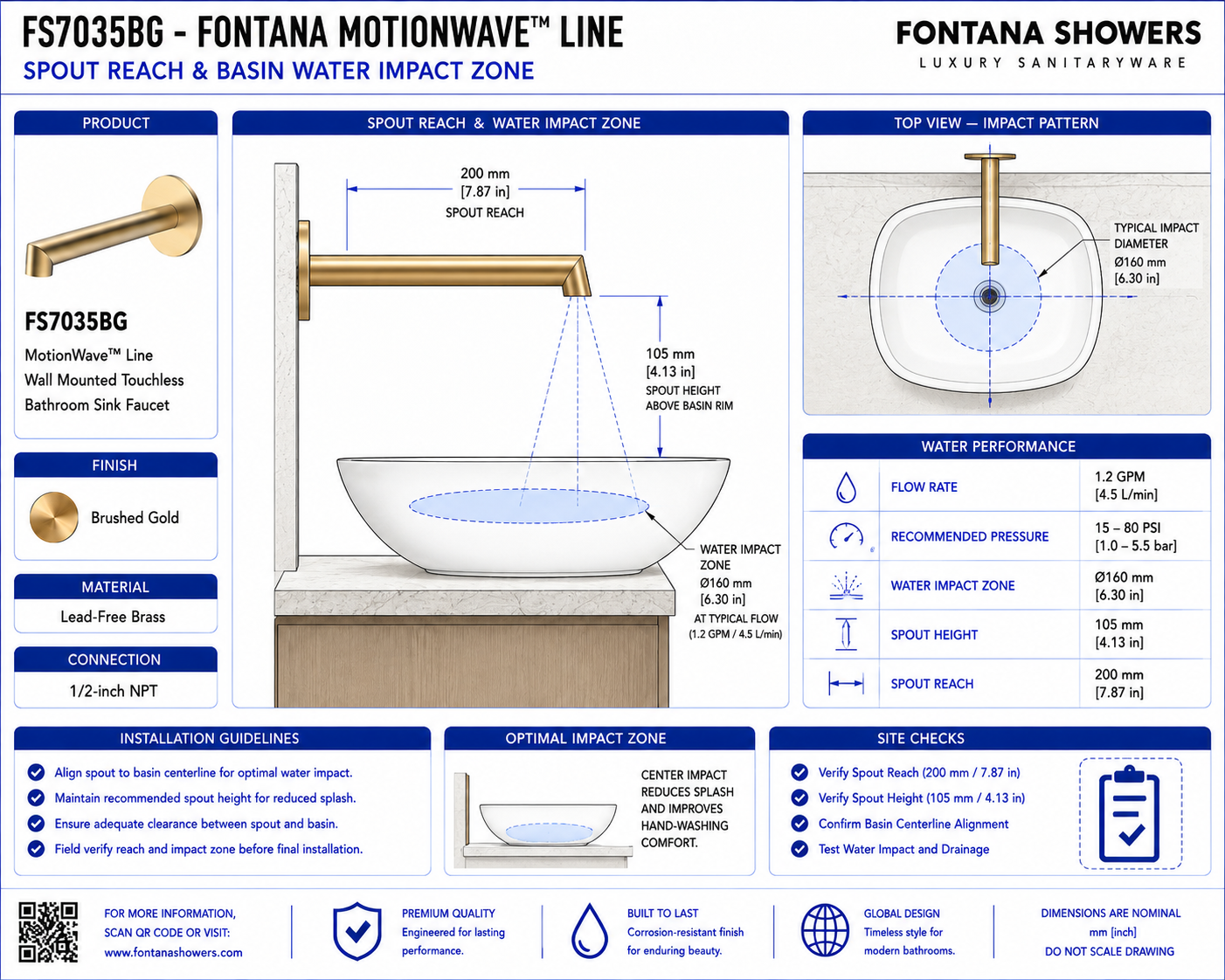
The detail should show the relationship between the finished-wall plane,
wall-mounted spout projection, basin rim, basin interior and intended water
landing area. The 6.93-inch spout reach should be coordinated with the selected
lavatory so the stream enters the usable basin zone without striking the rim
or creating excessive splash. Only verified manufacturer dimensions should be
included in final construction documents.
Complete Reach Section
Show the finished wall, wall-mounted spout, basin profile,
water stream and intended impact area in one coordinated section.
6.93-Inch Spout Reach
Show the horizontal projection from the finished-wall plane
to the faucet outlet.
Finished Wall Reference
Use the completed wall surface as the reference plane for
measuring faucet projection toward the basin.
Spout Outlet Position
Locate the outlet above the usable basin area rather than
directly over the rim or outside the bowl.
Basin Rim Relationship
Show the horizontal separation between the outlet and basin
rim to establish controlled water entry.
Basin Capture Zone
Identify the effective interior area of the lavatory intended
to receive the water stream.
Water Impact Point
Show the anticipated point where the water stream contacts
the basin interior during normal operation.
Water Stream Path
Show the discharge path from the faucet outlet toward the
selected basin impact zone.
Rear Basin Clearance
Maintain sufficient separation from the rear basin wall to
reduce water rebound toward the user.
Front Basin Clearance
Keep the impact point sufficiently inside the front basin
rim to limit water escape onto the surrounding surface.
Basin Depth
Review basin depth together with spout reach and outlet
position when evaluating splash performance.
Basin Bottom Clearance
Avoid directing the water stream onto a shallow basin surface
where rebound could increase splash.
Drain Relationship
Show the drain location relative to the water-impact point
without requiring the stream to land directly on the drain fitting.
Splash-Control Zone
Identify the preferred interior area where water impact can
remain contained within the basin.
Hand-Wash Zone
Coordinate spout projection so normal hand placement occurs
within the usable basin area.
Sensor Activation Zone
Coordinate the intended hand-detection field with the water
stream and basin wash zone.
Sensor-to-Basin Clearance
Keep reflective basin surfaces from remaining continuously
within the active sensing field where practical.
Vessel Basin Coordination
For above-counter basins, coordinate the increased rim height
and interior geometry with the fixed wall-mounted projection.
Undermount Basin Coordination
For undermount basins, coordinate the water stream with the
countertop opening and internal bowl geometry.
Countertop Edge Clearance
Where a countertop is present, position the water stream clear
of the rear deck and exposed counter edges.
Stream Alignment
Confirm the outlet is aligned with the basin centerline or
approved wash-zone location.
Operating Flow Review
Review the 1.2 GPM flow condition together with basin geometry
and impact location during commissioning.
User Approach Zone
Maintain the water-impact area within a comfortable hand-washing
position without forcing the user toward the basin edge.
Finished Water Zone
Show the final coordinated relationship between the faucet outlet,
basin and intended water-impact area.