Fontana Touchless Faucets™ | Architectural and Engineering Resource
Fontana MotionWave™ Line Brushed Gold Touchless Bathroom Faucet:
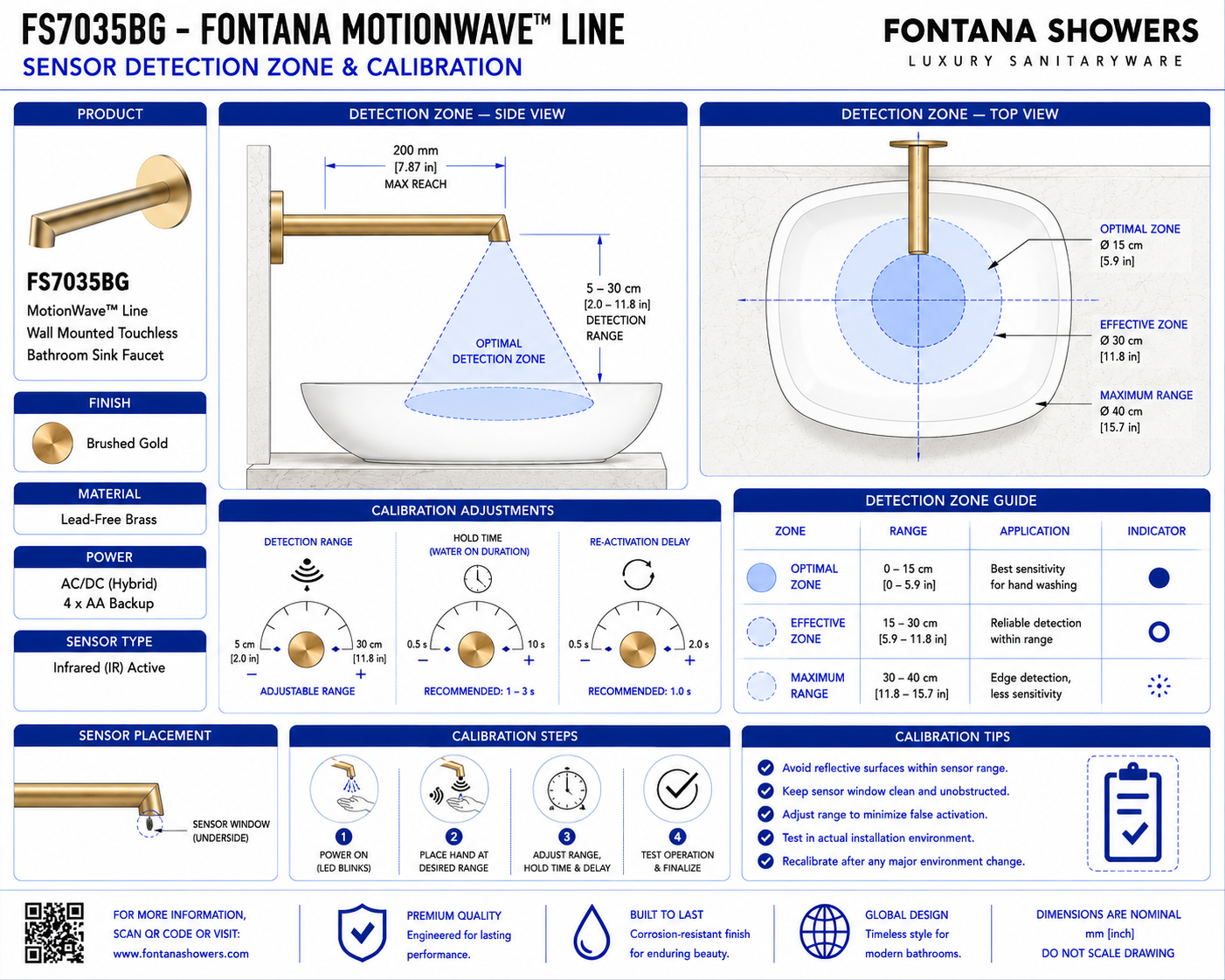
Sensor Zone & Calibration
This sensor-zone and calibration resource supports architects, plumbing engineers,
interior designers, contractors and installers coordinating the Fontana MotionWave™
Line FS7035BG wall-mounted touchless bathroom faucet. The detail identifies the
intended hand-detection area, sensor alignment, basin relationship, reflective-surface
clearance and final commissioning requirements.
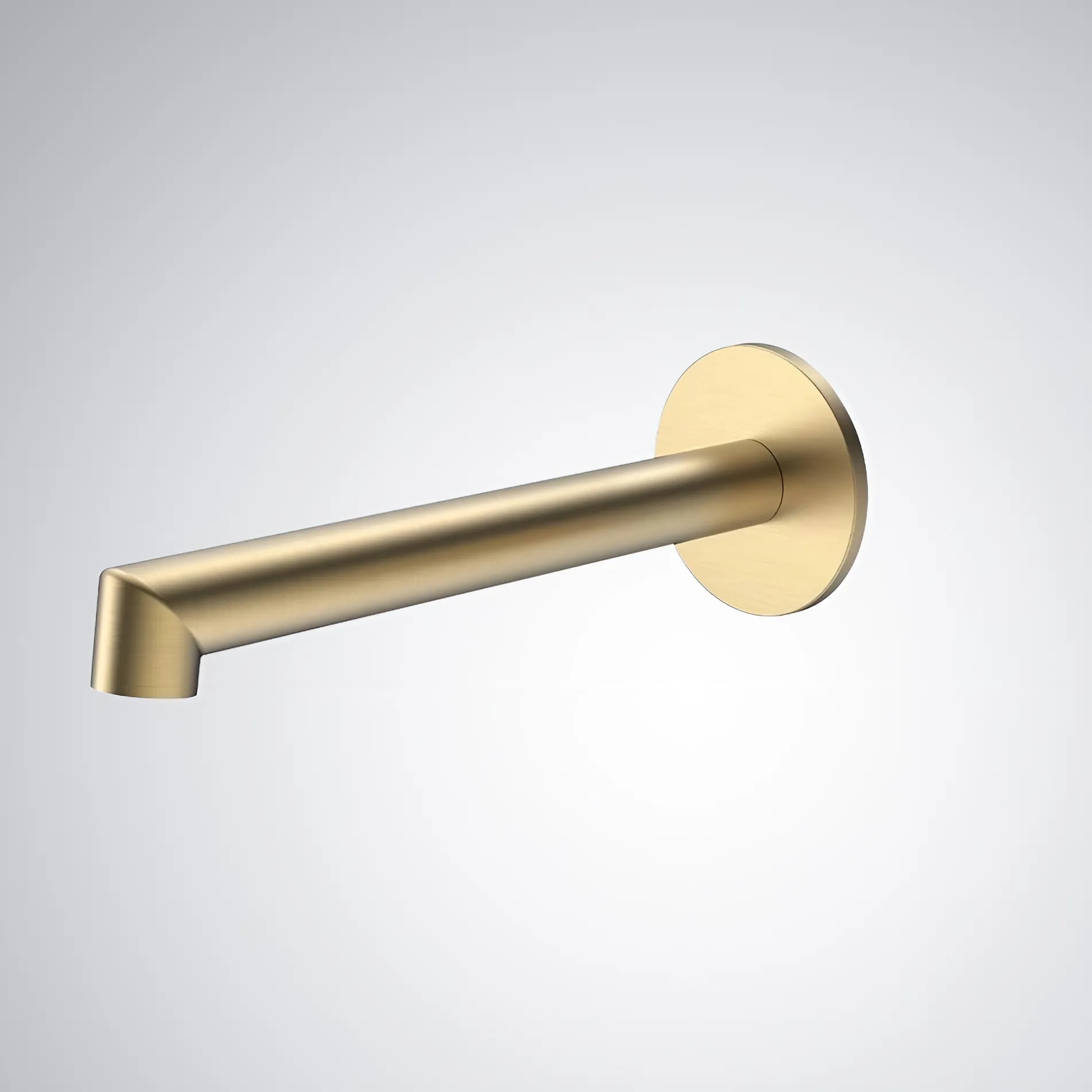
Fontana MotionWave™ Line FS7035BG Touchless Bathroom Faucet
The FS7035BG is a Brushed Gold wall-mounted touchless faucet designed
for automatic sensor activation and concealed installation.
- Model: FS7035BG
- Product type: Touchless bathroom faucet
- Installation: Wall mounted
- Operation: Automatic sensor activation
- Material: Lead-Free Brass
- Finish: Brushed Gold
- Valve included: Yes
- Valve type: Ceramic Valve
- Water connection: 1/2-inch NPT
- Flow rate: 1.2 GPM / 4.5 LPM
- Spout reach: 6.93 inches
- Installation type: Concealed wall installation
Sensor Detection & Calibration Scope
The sensor detail should show the intended hand-detection zone below the
wall-mounted faucet and its relationship to the basin, water stream,
finished wall and surrounding reflective surfaces. Final sensor calibration
should be completed only after the faucet, basin and architectural finishes
are installed.
Complete Sensor View
Show the faucet, sensor position, hand-detection zone,
basin and water stream in one coordinated installation view.
Sensor Position
Identify the sensing component relative to the faucet outlet
and finished-wall surface.
Detection Zone
Show the intended area where normal hand movement should
trigger automatic water flow.
Hand Approach Zone
Coordinate the sensing field with the natural hand position
below the faucet outlet.
Sensor Centerline
Show the sensor aligned with the intended wash zone and
faucet centerline.
Basin Clearance
Keep the basin rim and interior surfaces from remaining
unnecessarily within the active sensing field.
Reflective Surface Clearance
Review polished or reflective basin surfaces that could
contribute to unintended sensor activation.
Finished Wall Clearance
Coordinate the sensor position with reflective wall finishes,
backsplashes and nearby architectural surfaces.
Water Stream Relationship
Show the sensing zone in relation to the water-discharge
path and normal hand-washing position.
Spout Reach Relationship
Coordinate the sensor field with the 6.93-inch spout
projection and selected basin geometry.
Basin Rim Exclusion
Adjust the active field so the basin rim does not create
constant or intermittent triggering.
Drain Reflection Review
Check polished drain fittings or metallic basin components
that may reflect infrared energy toward the sensor.
Mirror Clearance
Where mirrors or reflective wall panels are nearby, review
their relationship to the sensor detection field.
Adjacent Fixture Clearance
Maintain separation from neighboring fixtures that could
enter the sensing field or cause unintended activation.
Front Activation Test
Test the faucet by approaching the basin from the normal
front user position.
Side Activation Test
Check sensor response from both sides of the normal
hand-washing area.
False-Trigger Test
Observe the faucet with the basin empty and verify that
stationary surfaces do not trigger water flow.
Activation Response
Confirm the faucet responds consistently when hands enter
the intended detection area.
Shut-Off Response
Remove hands from the sensing zone and verify that water
flow stops promptly and consistently.
Detection Stability
Confirm repeated hand movement produces reliable activation
without intermittent cycling.
Lighting Review
Observe sensor performance under the final installed
lighting conditions during commissioning.
Calibration Adjustment
Adjust the detection field as required so it responds to
users while excluding fixed surrounding surfaces.
Final Sensor Test
Complete repeated activation and shut-off cycles after
all basin and wall finishes are installed.
Commissioned Zone
Document the final usable detection area after successful
calibration and functional testing.
Engineering note:
Sensor-zone dimensions must not be based on estimated product measurements.
Confirm the sensor range, calibration requirements, basin relationship,
control configuration and commissioning criteria from the approved
FontanaShowers specification sheet or project submittal before final setup.
Required Sensor & Calibration Views
Front Sensor Elevation
Show the sensor position, faucet centerline, basin and
intended hand-detection zone.
Side Detection Section
Show the sensor field relative to the spout projection,
basin rim and interior surfaces.
Detection Zone Detail
Show the intended activation area beneath the faucet
outlet and above the basin.
Reflection Clearance View
Show nearby reflective basin, drain and wall surfaces
that should remain outside the active zone.
Hand Approach View
Show the normal user approach path entering the intended
sensor field.
Water Stream View
Show the relationship between sensor activation, hand
position and the faucet water stream.
Calibration View
Identify the final sensor field after adjustment and
commissioning.
Finished Installation
Show the commissioned sensor zone after the basin,
wall finishes and faucet are fully installed.
Recommended Sensor Calibration Sequence
1. Review Approved Submittals
Confirm the sensor configuration, control requirements
and commissioning information.
2. Complete Faucet Installation
Install and align the wall-mounted faucet before final
sensor calibration.
3. Complete Basin Installation
Install the final basin so all reflective and geometric
conditions are present.
4. Complete Wall Finishes
Finish surrounding tile, stone, mirrors and architectural
surfaces before final sensor adjustment.
5. Energize Faucet
Connect the approved operating power configuration and
confirm the sensor system initializes correctly.
6. Test Initial Detection
Move hands through the intended wash zone and observe
initial sensor response.
7. Review Fixed Surfaces
Check whether the basin, drain, backsplash or nearby
reflective surfaces cause unintended activation.
8. Adjust Detection Field
Refine the sensor range as required to recognize normal
hand movement without sensing fixed surfaces.
9. Test Multiple Approaches
Check activation from the front and both sides of the
intended hand-washing area.
10. Verify Shut-Off
Remove hands from the detection zone and confirm water
flow stops consistently.
11. Check False Activation
Leave the basin area empty and verify the faucet remains
off under normal room conditions.
12. Final Functional Test
Complete repeated activation cycles and confirm stable,
reliable touchless operation.
Architectural and MEP Coordination
Basin Coordination
Coordinate sensor calibration with the final basin geometry,
rim profile and finish.
Wall Coordination
Review nearby wall finishes, backsplashes and mirrors that
may influence sensor performance.
Plumbing Coordination
Confirm water delivery and valve response remain stable
during repeated sensor activation.
Electrical Coordination
Verify sensor, controller and power connections are secure
before calibration begins.
Lighting Coordination
Test the faucet under final installed lighting conditions
rather than temporary construction lighting.
Spout Coordination
Align the detection field with the faucet outlet and
intended water-delivery area.
User Coordination
Maintain a natural detection zone corresponding with
normal hand placement at the basin.
Maintenance Coordination
Retain access to control components needed for future
sensor adjustment and diagnostic testing.
Sensor & Calibration Components
-
Infrared sensor:
Touchless sensing component used to detect normal hand movement.
-
Detection zone:
Area where hand movement should initiate automatic faucet operation.
-
Hand-approach zone:
Normal user movement path toward the water stream.
-
Basin rim:
Fixed surface that should be reviewed during sensor commissioning.
-
Reflective basin surface:
Surface that may influence infrared sensor response depending on geometry and finish.
-
Drain fitting:
Reflective component that should be reviewed for possible sensor interaction.
-
Water stream:
Flow path associated with the normal hand-washing and sensor activation zone.
-
Electronic controller:
Control component receiving the sensor signal and managing faucet operation.
-
Sensor cable:
Low-voltage connection between the sensing assembly and control system.
-
Calibration zone:
Final commissioned detection field established after installation.
FontanaShowers Installation and Specification Resources
Professional Engineering and Accessibility References
Project verification:
This sensor-detection and calibration resource is intended for coordination
and does not replace an approved project submittal. The architect, plumbing
engineer, electrical engineer, interior designer and licensed installer should
verify final sensor range, basin relationship, reflective surfaces, controller
configuration, power requirements, commissioning criteria and locally adopted
codes before final calibration.
|
|
|