Home > Fontana MotionWave™ Line - Gold | 1/2-Inch NPT Water Supply Connection Detail

Fontana Touchless Faucets™ | Architectural and Engineering Resource

Fontana MotionWave™ Line Brushed Gold Touchless Bathroom Faucet: 1/2-Inch NPT Supply Connection

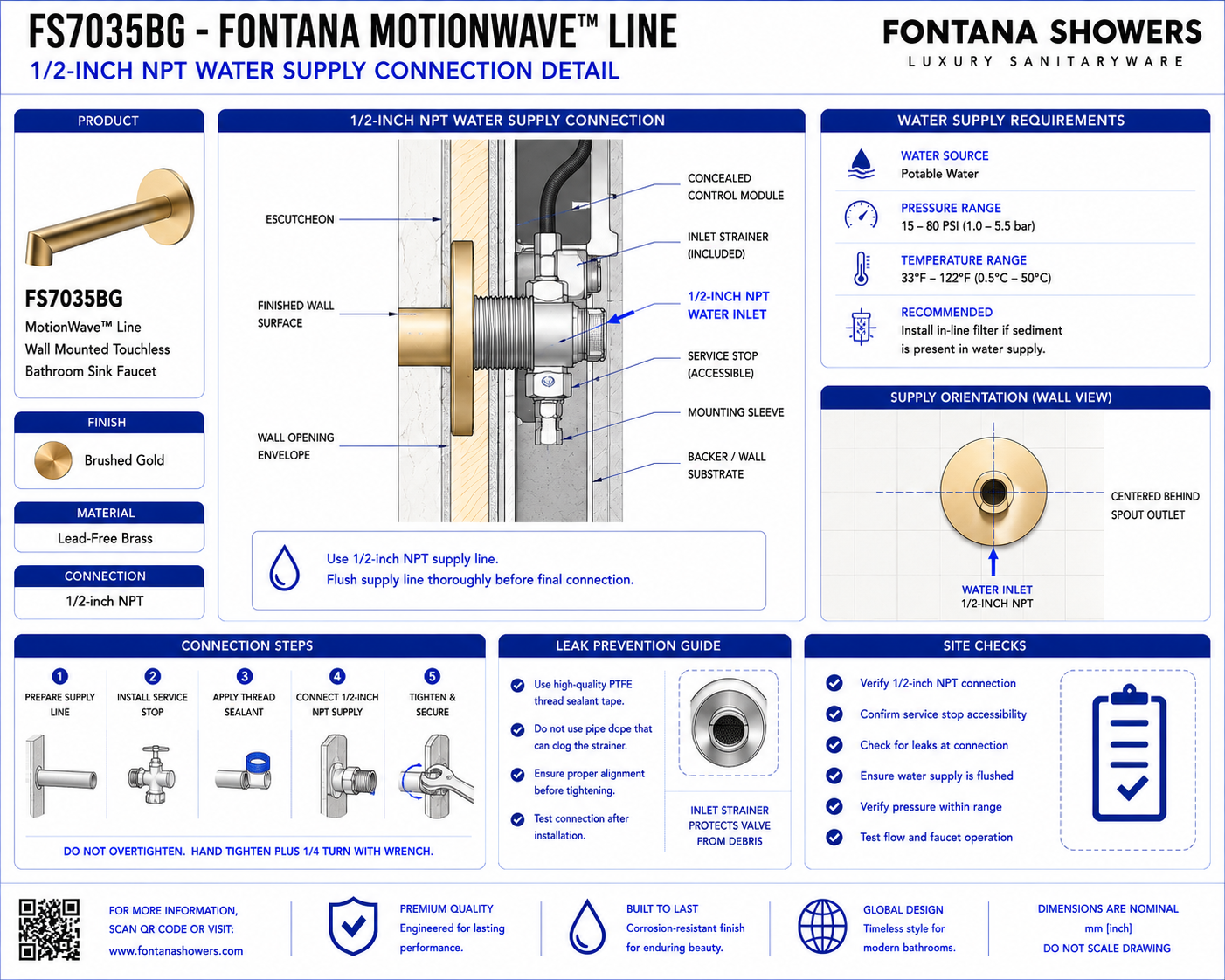
This water-supply connection resource supports architects, plumbing engineers, contractors and installers coordinating the Fontana MotionWave™ Line FS7035BG wall-mounted touchless bathroom faucet. The detail identifies the 1/2-inch NPT connection, supply-pipe alignment, valve relationship, joint-access zone and service requirements for concealed plumbing installation.

Fontana MotionWave™ Line FS7035BG Touchless Bathroom Faucet

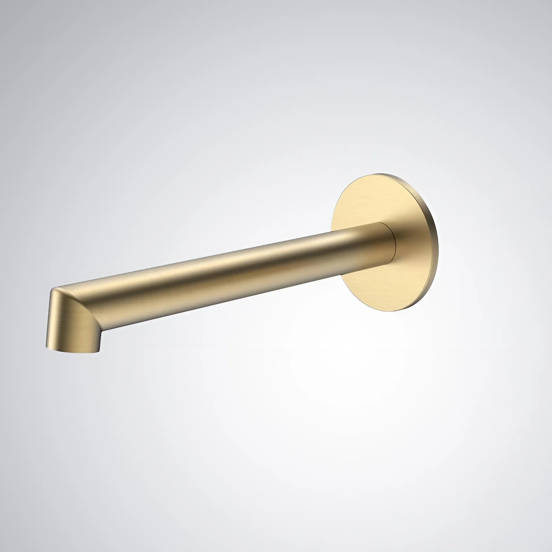
The FS7035BG is a Brushed Gold wall-mounted touchless faucet with concealed installation and a 1/2-inch NPT water-supply connection.

  • Model: FS7035BG
  • Product type: Touchless bathroom faucet
  • Installation: Wall mounted
  • Material: Lead-Free Brass
  • Finish: Brushed Gold
  • Valve included: Yes
  • Valve type: Ceramic Valve
  • Water connection: 1/2-inch NPT
  • Flow rate: 1.2 GPM / 4.5 LPM
  • Spout reach: 6.93 inches
  • Installation type: Concealed wall installation
  • Application: Commercial and architectural washrooms

NPT Water Supply Connection Scope

The connection detail should show the 1/2-inch NPT supply interface, concealed valve relationship, pipe alignment, flow direction and working clearance required for installation and maintenance. The supply connection should remain accessible and should not be subjected to excessive stress, misalignment or interference from adjacent wall construction. Only verified manufacturer dimensions should be used in final construction documents.

Complete Supply Connection

Show the building water supply, 1/2-inch NPT connection, concealed valve and outlet path in one coordinated detail.

1/2-Inch NPT Interface

Identify the threaded connection between the building water supply and concealed faucet assembly.

Supply Pipe Alignment

Keep the incoming water line aligned with the valve connection to avoid unnecessary side loading.

Thread Engagement

Provide proper threaded engagement in accordance with the approved product installation requirements.

Flow Direction

Show the intended direction of water movement from the building supply through the valve toward the faucet outlet.

Valve Inlet Position

Identify the inlet side of the concealed valve and its relationship to the supply pipe.

Valve Outlet Position

Show the downstream connection carrying water from the valve toward the wall-mounted faucet.

Connection Centerline

Align the supply connection with the concealed valve centerline and approved rough-in position.

Joint Clearance

Maintain sufficient working space around the threaded joint for assembly, inspection and future maintenance.

Tool Access Zone

Provide enough clearance to use appropriate installation tools without damaging surrounding construction.

Isolation Valve Access

Where an isolation valve is provided, keep it accessible for commissioning and future servicing.

Pipe Support

Support the building supply independently so its weight does not place unnecessary load on the faucet valve connection.

Valve Support

Secure the concealed valve to suitable backing or structure rather than relying on the supply pipe for support.

Wall Cavity Clearance

Keep the water connection clear of studs, blocking and adjacent concealed services.

Fitting Clearance

Maintain adequate space around fittings so connections can be inspected without obstruction.

Sealant Application Zone

Apply suitable thread-sealing material according to the approved installation instructions without contaminating the internal waterway.

Connection Orientation

Maintain the approved valve and fitting orientation so the connection remains accessible after installation.

Supply Stub-Out

Show the building supply stub-out positioned to connect directly to the concealed faucet assembly.

Wall Penetration Clearance

Where piping passes through framing or wall construction, maintain adequate clearance and protection around the pipe.

Moisture Separation

Keep electrical and sensor components separated from potential plumbing leak points where practical.

Leak Inspection Zone

Keep the threaded connection visible or service-accessible for pressure testing and leak inspection.

Pressure Test Point

Identify the supply connection as a required inspection location during system pressure testing.

Service Removal Clearance

Allow sufficient space for the valve or fitting to be disconnected without removing unrelated wall components.

Finished Supply Assembly

Show the completed 1/2-inch NPT connection securely supported, correctly aligned and accessible for future inspection.

Engineering note: Water-supply connection dimensions must not be based on estimated product measurements. Confirm the 1/2-inch NPT connection, valve orientation, threaded engagement, supply alignment and service-clearance requirements from the approved FontanaShowers specification sheet or project submittal before plumbing rough-in.

Required Supply Connection Views

Connection Section

Show the building supply, 1/2-inch NPT connection, concealed valve and downstream water path.

Valve Connection View

Show the valve inlet and outlet orientation together with the threaded water-supply connection.

Supply Stub-Out View

Show the position and alignment of the building water supply before final connection.

Threaded Joint Detail

Show the NPT connection, threaded engagement and required working clearance.

Flow Direction View

Show the direction of water flow through the concealed valve toward the faucet.

Support Detail

Show independent pipe and valve support within the wall cavity.

Service Clearance View

Show sufficient access around the connection for tools, inspection and replacement.

Finished Connection

Show the final supply assembly after pressure testing and wall coordination are complete.

Recommended Supply Connection Sequence

1. Review Approved Submittals

Confirm the final faucet, valve arrangement and 1/2-inch NPT connection requirements.

2. Establish Rough-In Position

Set the water-supply centerline according to the approved faucet and valve location.

3. Install Pipe Support

Secure the building supply so the connection remains stable during assembly and operation.

4. Position Concealed Valve

Mount the valve securely and align its inlet with the incoming water-supply line.

5. Prepare NPT Threads

Prepare the threaded connection using the approved sealing method and clean installation practices.

6. Make Supply Connection

Connect the 1/2-inch NPT supply without forcing or misaligning the concealed valve.

7. Verify Flow Direction

Confirm the valve is oriented for water flow toward the faucet outlet.

8. Check Mechanical Stress

Verify the piping does not twist, pull or place side load on the valve connection.

9. Flush Water Supply

Flush the building supply before final commissioning so construction debris does not enter the faucet assembly.

10. Pressure Test

Pressurize the system and inspect the NPT joint and adjacent fittings for leakage.

11. Verify Service Access

Confirm the supply and valve connections remain reachable before permanent finishes are completed.

12. Final Inspection

Verify the finished connection is aligned, supported, leak-free and ready for faucet commissioning.

Architectural and MEP Coordination

Plumbing Coordination

Coordinate the 1/2-inch supply line, valve orientation and connection access with the approved faucet rough-in.

Structural Coordination

Provide suitable support for the supply and concealed valve without obstructing the connection zone.

Wall Coordination

Keep framing and wall construction clear of the threaded connection and required tool-access area.

Valve Coordination

Confirm valve inlet and outlet orientation before the concealed wall assembly is closed.

Electrical Separation

Keep electronic control components and wiring separated from plumbing joints and potential leak locations.

Service Coordination

Maintain access for future leak inspection, valve service and connection replacement.

Pressure-Test Coordination

Complete testing before permanent construction prevents visual inspection of concealed connections.

Maintenance Coordination

Arrange piping so normal servicing does not require unnecessary demolition of finished wall surfaces.

Water Supply Connection Components

  • Building water supply: Incoming water line serving the wall-mounted faucet assembly.
  • 1/2-inch NPT connection: Threaded plumbing interface connecting the water supply to the concealed faucet system.
  • Supply stub-out: Building-side connection positioned at the approved faucet rough-in location.
  • Concealed valve: Internal water-control component installed downstream of the supply connection.
  • Valve inlet: Connection point receiving water from the building supply.
  • Valve outlet: Connection carrying controlled water toward the faucet.
  • Thread seal: Approved sealing material used at the NPT connection.
  • Pipe support: Structural support maintaining stable water-supply alignment.
  • Isolation valve: Accessible shutoff provision used for commissioning and maintenance where provided.
  • Service clearance: Working area around the connection required for inspection and future servicing.

Professional Engineering and Accessibility References

Project verification: This 1/2-inch NPT water-supply connection resource is intended for coordination and does not replace an approved project submittal. The architect, plumbing engineer and licensed installer should verify final connection size, valve orientation, pipe alignment, thread-sealing requirements, water pressure, service access and locally adopted plumbing requirements before rough-in or installation.