Fontana Touchless Faucets™ | Architectural and Engineering Resource
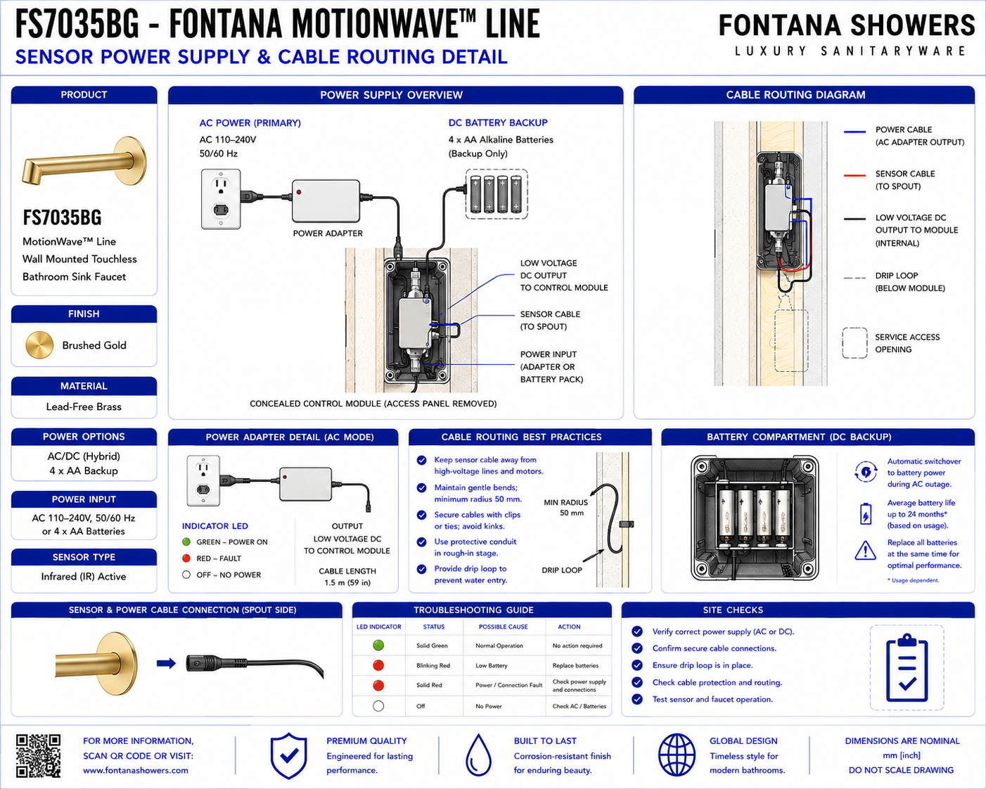
Fontana MotionWave™ Line Touchless Bathroom Faucet:
Sensor Power & Cable Routing
This sensor-power and cable-routing resource supports architects, plumbing
engineers, electrical engineers, contractors and installers coordinating the
Fontana MotionWave™ Line FS7035BG wall-mounted touchless bathroom faucet.
The detail identifies the power-supply location, controller relationship,
sensor wiring, valve-control cable path and separation from plumbing and
potential moisture sources.
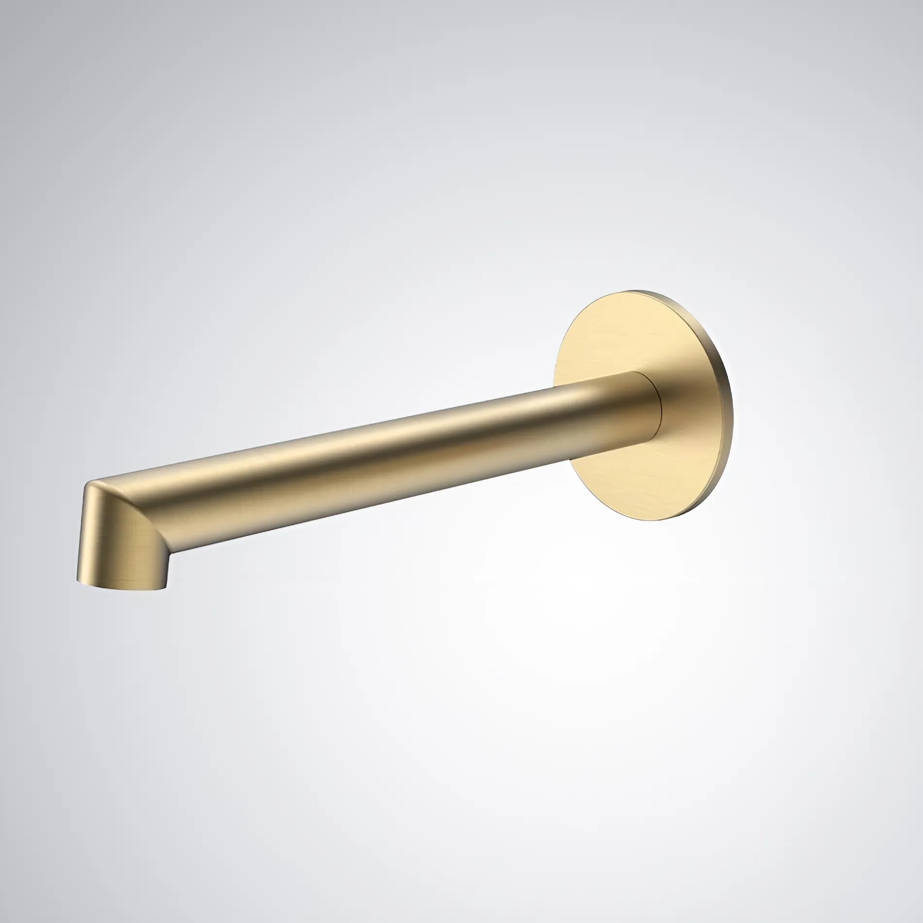
Fontana MotionWave™ Line FS7035BG Touchless Bathroom Faucet
The FS7035BG is a Brushed Gold wall-mounted touchless bathroom
faucet with concealed sensor, control and power components.
- Model: FS7035BG
- Product type: Touchless bathroom faucet
- Installation: Wall mounted
- Operation: Automatic sensor activation
- Material: Lead-Free Brass
- Finish: Brushed Gold
- Valve included: Yes
- Valve type: Ceramic Valve
- Water connection: 1/2-inch NPT
- Flow rate: 1.2 GPM / 4.5 LPM
- Spout reach: 6.93 inches
- Installation type: Concealed wall installation
Power & Cable Routing Scope
The detail should show the relationship between the faucet sensor,
electronic controller, approved power source, control valve and low-voltage
cable routes. Wiring should be organized, protected and kept clear of
plumbing joints, sharp edges, moving hardware and areas exposed to moisture.
Only verified manufacturer requirements should be used in final construction
documents.
Complete Power Layout
Show the faucet sensor, controller, power source, control valve
and cable routes in one coordinated installation view.
Power Supply Position
Locate the approved power component in a dry and accessible
location within the permitted connection range.
Controller Position
Mount the electronic controller where sensor, power and
valve-control cables can connect without excessive tension.
Sensor Cable Route
Route the low-voltage sensor cable from the faucet toward
the controller using a protected and serviceable path.
Valve-Control Cable
Show the electrical connection between the controller and
sensor-controlled water valve.
Power Cable Route
Provide a direct and protected path between the approved
power source and electronic controller.
Cable Reach
Position concealed components within the approved cable
length so extensions or stressed connections are avoided.
Cable Support
Support low-voltage wiring at appropriate intervals so
cables do not hang loosely within the wall cavity.
Connector Access
Keep all sensor, controller and valve connectors visible
and reachable for commissioning and diagnostic testing.
Plumbing Separation
Maintain separation between electrical wiring and water
connections wherever practical.
Moisture Clearance
Keep the controller, connectors and power components away
from locations subject to leaks or standing moisture.
Sharp Edge Protection
Protect cables where they pass near metal framing, wall
openings or other surfaces that could damage insulation.
Wall Penetration
Where wiring passes through framing or wall materials,
provide a protected and coordinated penetration.
Cable Bend Radius
Avoid sharp cable bends that could damage wiring or place
excessive stress on connectors.
Slack Management
Provide controlled service slack where required without
allowing loose cable loops to interfere with plumbing.
Moving Hardware Clearance
Keep wiring clear of access-panel hardware, hinges or
other moving components.
Valve Cable Connection
Show the control cable securely connected to the valve
and accessible for future replacement.
Sensor Connection
Show the faucet sensor cable connected to the designated
controller input without tension or twisting.
Power Connection
Show the approved power connection to the controller in
a protected and serviceable location.
Access Panel Relationship
Coordinate the power and control components with the
planned service-access opening.
Service Loop
Provide reasonable cable movement for servicing without
creating excessive loose wiring.
Component Labeling
Label sensor, power and valve-control connections where
appropriate to support future maintenance.
Diagnostic Access
Keep connectors and controller interfaces accessible for
testing without disturbing finished surfaces.
Finished Cable Layout
Show the completed wiring arrangement organized, supported
and separated from plumbing and moisture sources.
Engineering note:
Power and cable-routing dimensions must not be based on estimated product
measurements. Confirm the approved power configuration, controller location,
cable lengths, connector requirements and service clearances from the
FontanaShowers specification sheet or project submittal before wall fabrication.
Required Power & Routing Views
Electrical Layout
Show the faucet sensor, controller, power source and
control-valve connection.
Side Wall Section
Show cable routes within the wall cavity together with
plumbing and service clearances.
Sensor Cable View
Show the low-voltage route from the faucet sensor to
the controller.
Valve Cable View
Show the controller-to-valve control cable and accessible
connection points.
Power Connection View
Show the approved power source and its connection to
the electronic controller.
Cable Support Detail
Show cable clips, supports and protection from sharp
edges or nearby plumbing.
Service Access View
Show the working area required to disconnect and test
power and control components.
Finished Routing Layout
Show the final coordinated cable arrangement after
plumbing and wall construction are complete.
Recommended Cable Routing Sequence
1. Review Approved Submittals
Confirm the final power arrangement, controller,
sensor and valve-control requirements.
2. Establish Component Locations
Locate the controller, valve and approved power source
before routing concealed wiring.
3. Verify Cable Reach
Confirm all components remain within the approved cable
length before installation.
4. Plan Cable Paths
Establish protected routes clear of plumbing joints,
sharp edges and moving hardware.
5. Install Cable Supports
Provide suitable clips or supports before wall cavities
become difficult to access.
6. Route Sensor Cable
Run the sensor cable from the faucet toward the controller
without excessive tension or sharp bends.
7. Route Valve Cable
Run the control cable between the controller and valve
using a separate protected route where practical.
8. Connect Power
Connect the approved power source according to the
product installation requirements.
9. Secure Connectors
Confirm all sensor, valve and power connectors are
fully seated and protected.
10. Verify Moisture Separation
Check that wiring and power components remain clear
of potential leak locations.
11. Test Control System
Energize the system and confirm sensor input, controller
response and valve operation.
12. Final Routing Inspection
Confirm all wiring remains organized, supported and
accessible before permanent finishes are completed.
Power & Control Commissioning
Power-Up Test
Energize the system and confirm the controller initializes
without abnormal operation.
Sensor Signal Test
Activate the sensor and verify the controller receives
a consistent detection signal.
Valve Response Test
Confirm the control valve responds correctly to controller
commands during activation and shut-off.
Connector Inspection
Inspect all electrical connectors for full engagement,
dry conditions and secure installation.
Cable Stress Check
Verify no cable is stretched, pinched or loaded by
adjacent plumbing or wall components.
False Activation Review
Confirm cable routing and connector conditions do not
contribute to intermittent sensor operation.
Service Access Test
Confirm connectors and power components can be reached
without unnecessary removal of permanent finishes.
Final Functional Test
Complete repeated activation and shut-off cycles to
confirm reliable powered operation.
Architectural and MEP Coordination
Electrical Coordination
Coordinate the approved power source, controller and
low-voltage wiring with project electrical requirements.
Plumbing Coordination
Maintain separation between wiring and plumbing joints
while preserving service access to both systems.
Wall Coordination
Plan cable routes before framing and permanent finishes
restrict access to the wall cavity.
Structural Coordination
Protect wiring where it passes around framing, blocking
or other structural components.
Moisture Coordination
Keep electronic components and connectors away from
likely leak paths and wet areas.
Access Coordination
Locate service openings so controller, power and
connection points remain accessible.
Sensor Coordination
Route sensor wiring without creating unnecessary distance
or interference with the faucet sensing system.
Maintenance Coordination
Organize cables and connectors so future diagnostic
testing and component replacement remain practical.
Power & Routing Components
-
Infrared sensor:
Touchless sensing component providing the user-activation signal.
-
Sensor cable:
Low-voltage wiring connecting the faucet sensor to the electronic controller.
-
Electronic controller:
Control component receiving the sensor signal and managing faucet operation.
-
Power supply:
Approved power component serving the sensor and electronic control system.
-
Valve-control cable:
Low-voltage connection between the controller and sensor-controlled valve.
-
Sensor control valve:
Electrically operated valve controlling water flow in response to the control system.
-
Cable connector:
Serviceable electrical interface joining sensor, controller, power or valve wiring.
-
Cable support:
Clip or support used to organize concealed low-voltage wiring.
-
Protected penetration:
Wall or framing opening through which wiring passes without contacting sharp edges.
-
Service-access zone:
Clear area providing access to the controller, power source and cable connections.
FontanaShowers Installation and Specification Resources
Professional Engineering and Accessibility References
Project verification:
This sensor-power and cable-routing resource is intended for coordination
and does not replace an approved project submittal. The architect, plumbing
engineer, electrical engineer and licensed installer should verify final power
configuration, controller location, cable lengths, connector requirements,
valve relationship, moisture separation, service access and locally adopted
codes before rough-in or installation.
|
|
|