Fontana Touchless Faucets™ | Architectural and Engineering Resource
Fontana MotionWave™ Line Brushed Gold Touchless Bathroom Faucet:
BIM / MEP Coordination
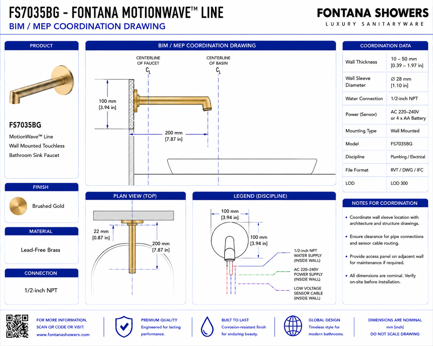
This BIM / MEP coordination resource supports architects, plumbing engineers,
electrical engineers, BIM coordinators, contractors and installers integrating
the Fontana MotionWave™ Line FS7035BG wall-mounted touchless bathroom faucet
into coordinated project models and construction drawings. The detail identifies
the faucet location, concealed valve, water supply, sensor components, power
requirements, cable routing and service-access zones requiring multidisciplinary
coordination.
Fontana MotionWave™ Line FS7035BG Touchless Bathroom Faucet
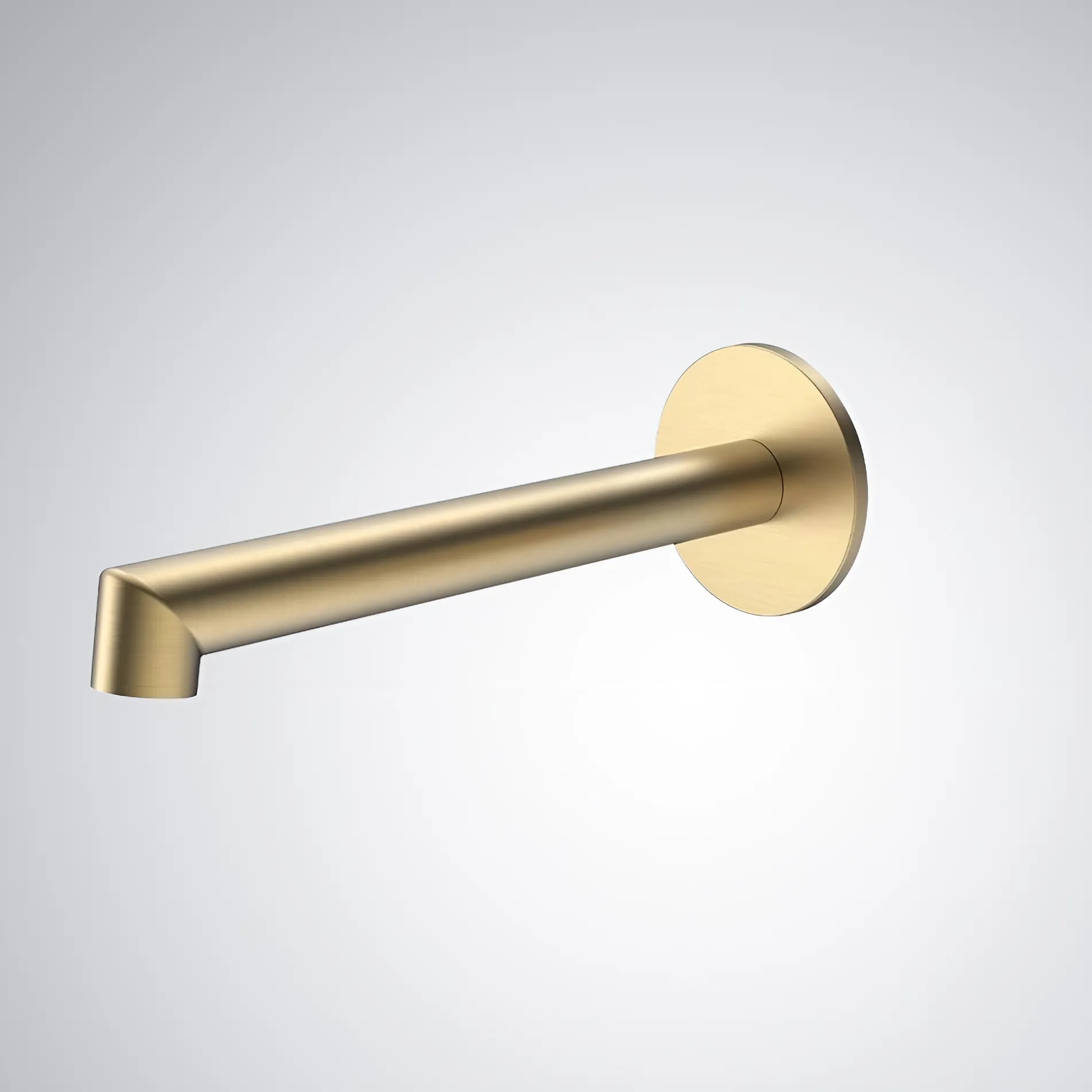
The FS7035BG is a Brushed Gold wall-mounted touchless bathroom faucet
with concealed plumbing, sensor-control and service-access requirements.
- Model: FS7035BG
- Product type: Touchless bathroom faucet
- Installation: Wall mounted
- Operation: Automatic sensor activation
- Material: Lead-Free Brass
- Finish: Brushed Gold
- Valve included: Yes
- Valve type: Ceramic Valve
- Water connection: 1/2-inch NPT
- Flow rate: 1.2 GPM / 4.5 LPM
- Spout reach: 6.93 inches
- Installation type: Concealed wall installation
BIM / MEP Coordination Scope
The coordinated drawing should show the wall-mounted faucet, basin,
concealed valve, water-supply route, sensor-control system, power source,
cable pathways, wall construction and service-access provisions within
a common architectural and MEP reference. Model dimensions and connection
locations should be based only on approved manufacturer information.
Complete Coordination Model
Show architectural, plumbing and electrical elements associated
with the faucet in one coordinated BIM / MEP arrangement.
Faucet Location
Show the wall-mounted faucet positioned relative to the basin,
wall finish and architectural reference grid.
Faucet Centerline
Establish the horizontal and vertical centerlines used by
architectural and MEP disciplines for coordinated placement.
Basin Relationship
Show the basin geometry, rim position and water-impact zone
in relation to the wall-mounted spout.
Spout Projection
Model the 6.93-inch spout reach from the finished-wall plane
toward the intended basin capture zone.
Finished Wall Plane
Use the final architectural surface as the reference for
faucet projection and concealed rough-in depth.
Wall Opening
Show the coordinated penetration required for the faucet
connection without conflicting with finish or structural elements.
Concealed Valve Position
Locate the valve within the wall cavity where supply, control
and service connections remain accessible.
1/2-Inch NPT Supply
Show the incoming water-supply connection coordinated with
the concealed valve location and rough-in centerline.
Supply Pipe Route
Model the plumbing route from the building supply to the
faucet assembly without interference from framing or other services.
Flow Direction
Identify the direction of water movement through the valve
toward the wall-mounted faucet outlet.
Sensor Position
Show the sensor location relative to the faucet outlet,
basin and intended hand-detection area.
Sensor Zone
Represent the intended hand-activation zone and keep it clear
of fixed reflective surfaces where practical.
Controller Location
Show the electronic controller in a dry and serviceable
location coordinated with cable reach.
Power Supply Location
Coordinate the approved power component with the controller
and project electrical layout.
Sensor Cable Route
Show the low-voltage route between the faucet sensor and
electronic controller.
Valve-Control Cable
Show the control wiring between the controller and water-control
valve within the concealed installation zone.
Plumbing Separation
Maintain appropriate separation between wiring, electronic
components and plumbing joints.
Structural Clearance
Check studs, blocking and structural members for conflicts
with the valve, piping and cable routes.
Finish Clearance
Coordinate tile, stone and wall build-up with exposed trim,
concealed connection depth and service requirements.
Waterproofing Interface
Show faucet penetrations coordinated with the project
waterproofing or moisture-control system.
Service Access Zone
Reserve sufficient space to inspect, test and replace
concealed plumbing and control components.
Access Panel Position
Where required, locate the access opening directly in
relation to the primary serviceable components.
Clash-Free Final Layout
Show the final coordinated arrangement after architectural,
plumbing, electrical and structural conflicts have been resolved.
Engineering note:
BIM / MEP coordination dimensions must not be based on estimated product
measurements. Confirm faucet dimensions, valve location, 1/2-inch NPT
connection, cable reach, power configuration and service clearances from
the approved FontanaShowers specification sheet or project submittal before
model sign-off or construction.
Required BIM / MEP Views
Front Coordination Elevation
Show the faucet, basin, centerlines, concealed valve and
associated MEP components.
Side Coordination Section
Show spout projection, wall construction, valve depth,
piping and service clearance.
Architectural Plan View
Show basin position, faucet centerline, adjacent fixtures
and required clearances.
MEP Plan View
Show water supply, concealed valve, controller, power
and cable-routing zones.
Plumbing Diagram
Show building supply, 1/2-inch NPT connection, control
valve and faucet water path.
Electrical Diagram
Show sensor, controller, power source and valve-control
cable connections.
Clash Detection View
Show the fixture system against framing, drainage,
electrical and adjacent building services.
Final Coordination View
Show the approved multidisciplinary layout after all
identified conflicts have been resolved.
Recommended BIM Coordination Sequence
1. Review Approved Submittals
Confirm final faucet dimensions, connections, controls
and installation requirements before modeling.
2. Establish Architectural References
Set finished-wall, basin and fixture centerlines from
the coordinated architectural model.
3. Place Faucet Geometry
Position the wall-mounted faucet using approved dimensions
and the final basin relationship.
4. Add Concealed Valve
Model the valve within the wall cavity at the coordinated
connection and service location.
5. Route Water Supply
Connect the plumbing model to the 1/2-inch NPT faucet
supply interface.
6. Add Control Components
Place the sensor controller, valve-control equipment and
power components within approved connection reach.
7. Route Cables
Model sensor, valve-control and power routes while avoiding
conflicts with plumbing and structure.
8. Add Service Zones
Reserve maintenance and removal clearances around concealed
components.
9. Run Clash Detection
Check the faucet system against structure, drainage,
electrical services and architectural construction.
10. Resolve Conflicts
Adjust coordinated systems without changing verified faucet
requirements or reducing required service access.
11. Review Discipline Models
Confirm architectural, plumbing and electrical models use
the same approved fixture reference.
12. Issue Coordinated Drawing
Publish the final approved BIM / MEP layout for construction
and field verification.
Discipline Coordination Requirements
Architectural Coordination
Confirm wall finish, basin location, faucet centerline
and visible trim relationship.
Plumbing Coordination
Confirm water-supply route, connection size, valve location
and service isolation.
Electrical Coordination
Confirm power source, controller location, cable routing
and connector access.
Structural Coordination
Confirm blocking, framing and wall support do not conflict
with concealed equipment.
Interior Coordination
Coordinate tile, stone, mirror and finish conditions with
the sensor and trim interface.
Waterproofing Coordination
Integrate wall penetrations with the project moisture-control
and sealing strategy.
Facilities Coordination
Confirm serviceable components remain accessible for routine
inspection and future replacement.
Field Coordination
Verify actual site dimensions against the coordinated model
before concealed rough-in is finalized.
BIM / MEP Model Components
-
Wall-mounted faucet:
Visible Brushed Gold fixture represented in the architectural model.
-
Faucet centerline:
Common reference used for architectural and MEP placement.
-
Lavatory basin:
Architectural fixture geometry coordinated with spout reach and water impact.
-
Concealed valve:
Internal water-control component represented within the wall cavity.
-
1/2-inch NPT connection:
Plumbing connection point serving the touchless faucet assembly.
-
Water supply:
Plumbing route connecting the building system to the concealed valve.
-
Infrared sensor:
Touchless sensing component associated with automatic faucet operation.
-
Electronic controller:
Control component coordinating sensor and valve operation.
-
Power component:
Approved electrical source serving the electronic control system.
-
Sensor cable:
Low-voltage connection between the faucet sensor and controller.
-
Valve-control cable:
Control connection between the electronic controller and water valve.
-
Service-access zone:
Reserved clearance required around concealed serviceable components.
FontanaShowers Installation and Specification Resources
Professional Engineering and Coordination References
Project verification:
This BIM / MEP coordination resource is intended for multidisciplinary
coordination and does not replace an approved project submittal. The architect,
plumbing engineer, electrical engineer, BIM coordinator and licensed installer
should verify final dimensions, faucet centerlines, basin compatibility,
connection requirements, valve location, cable reach, power configuration,
service clearances and locally adopted codes before model approval or construction.
|
|
|