Fontana Touchless Faucets™ | Architectural and Engineering Resource
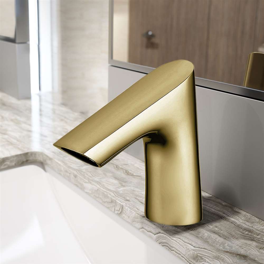
Fontana Commercial Brushed Gold Touchless Automatic Sensor Faucet:
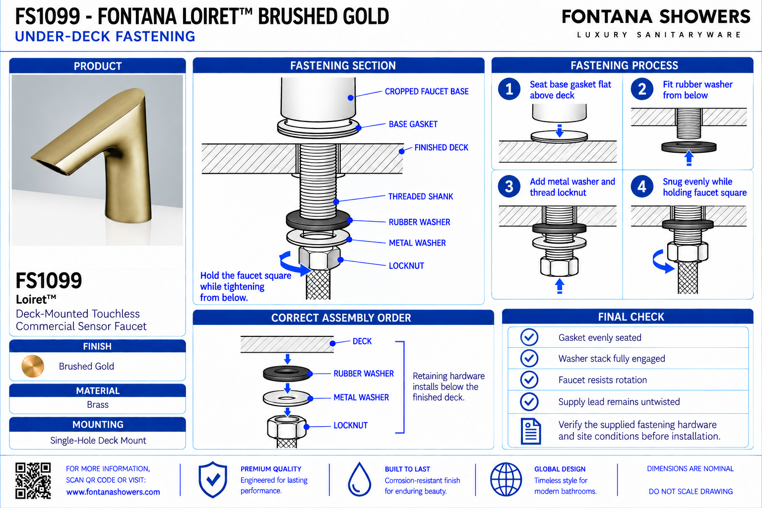
Under-Deck Fastening
This installation resource supports architects, plumbing engineers,
contractors, installers and facility managers coordinating the FS1099
fastening assembly beneath a commercial lavatory deck. The detail
establishes the threaded mounting tube, rubber washer, metal washer,
mounting nut and locking screws in relation to the countertop underside.
Maintain access for tightening and inspection while keeping the flexible
water pipe and sensor cable clear of the clamping surfaces.
Fontana FS1099 Under-Deck Mounting Assembly
The fastening assembly clamps the faucet to the deck through its
threaded mounting tube. Install the rubber washer against the
countertop underside, followed by the metal washer and mounting
nut. Align the faucet body before securing the nut and locking
screws as directed in the installation guide.
- Model: FS1099
- Finish: Brushed Gold
- Installation: Single-hole deck mount
- Overall height: 6 inches / 152.4 mm
- Base dimension shown: 1.5 inches / 38.1 mm
- Upper-body dimension shown: 0.5 inch / 12.7 mm
- Mounting-hole diameter: 1.26–1.38 inches / 32–35 mm
- Maximum countertop thickness without deck plate: 1.38 inches / 35 mm
- Above-deck seal: O-ring in the faucet’s bottom groove
- Under-deck assembly: Rubber washer, metal washer, mounting nut and locking screws
- Mounting interface: Threaded tube through the deck opening
- Protected routing: Flexible water pipe and sensor cable clear of fastening surfaces
Required Under-Deck Fastening Drawing Package
Organize the drawing around a sectional mounting detail and an
exploded view of the underside hardware. Identify the countertop
bearing surface, component order and threaded engagement. Include
the hose and cable routes alongside the fastening assembly so the
installer can distinguish the clamping interface from the service
connections.
Mounting Section
Show the faucet base above the finished deck and the fastening
assembly beneath it. Reference the countertop thickness and
illustrate the threaded tube passing through the opening with
sufficient access to assemble the underside components.
Rubber Washer Placement
Locate the rubber washer against the deck underside. Show it
seated around the mounting tube without folding, displacement
or interference from the hose and sensor cable.
Metal Washer Placement
Position the metal washer beneath the rubber washer as shown
in the installation assembly. Check that its bearing surface
remains clear of obstructions and seats evenly before the
mounting nut is tightened.
Mounting Nut Engagement
Show the mounting nut engaging the threaded tube beneath the
washer assembly. Inspect thread alignment during assembly and
confirm that the nut advances without cross-threading or
interference from routed components.
Locking Screw Access
Identify the locking screws associated with the mounting nut.
Show a practical tool approach and preserve access after the
basin, supports and cabinetry are installed.
Hose and Cable Separation
Illustrate the flexible water pipe and sensor cable outside
the washer-bearing and screw-contact areas. Keep both components
free from compression, sharp bends and contact with threaded
edges.
Underside Bearing Clearance
Coordinate the washer footprint with basin returns, countertop
reinforcement and support brackets. Identify any obstruction
that would prevent the assembly from bearing evenly against
the deck underside.
Final Stability Inspection
Confirm that the faucet remains aligned and its base seats
evenly on the finished deck. Inspect the fastening assembly
and verify that the hose and cable remain unstrained after
the control equipment is connected.
Engineering note:
Mounting-hole and countertop-thickness limits follow the FS1099
installation guide. Product-body dimensions follow the specification
drawing; their millimeter equivalents are calculated conversions.
The base dimension is not the drilling diameter. No fastening torque,
minimum thread-engagement length or alternative reinforcement detail
is established here. Confirm the supplied hardware and obtain
manufacturer guidance where countertop construction prevents the
illustrated assembly from seating correctly.
Under-Deck Fastening Installation Sequence
1. Inspect the Bearing Area
Check the countertop underside around the penetration.
Confirm that basin geometry, reinforcement and supports leave
space for the washers, mounting nut and tightening tools.
2. Support the Faucet Body
Seat the faucet on the finished deck with the base O-ring
correctly positioned. Support its orientation while the
underside components are installed.
3. Install the Washers
Place the rubber washer onto the threaded tube against the
deck underside, then install the metal washer. Keep the hose
and cable clear and check that both washers sit evenly.
4. Engage the Mounting Nut
Start the mounting nut on the threaded tube and check its
alignment. Position the faucet toward the intended washing
area before completing the fastening operation.
5. Secure the Assembly
Secure the mounting nut and locking screws according to the
installation guide. Observe the faucet base and washer seating
during tightening, and stop if the countertop or components
show distortion.
6. Verify and Connect
Confirm body stability, alignment and protected routing.
Complete the service connections, inspect for leaks and
retain access to the fastening assembly for future maintenance.
Architectural and MEP Coordination Considerations
Effective Deck Thickness
Include local build-ups and reinforcing layers when checking
the mounting interface. Confirm compatibility with the supplied
threaded tube and fastening assembly before fabrication.
Bearing-Surface Continuity
Check that the underside assembly has a suitable seating area.
Resolve conflicts with ribs, adhesive build-ups or basin returns
through an approved detail before installation.
Tool Approach
Reserve working space for the mounting nut and locking screws.
Evaluate access with the actual basin installed, including
the effect of brackets, plumbing and cabinet panels.
Connection Independence
Arrange the water pipe and cable so their routing does not
pull against the faucet body. Support connected equipment
independently and preserve slack for servicing.
Maintenance Removal
Keep the fastening components reachable for future faucet
removal. Coordinate access panels and removable cabinetry
before permanent finishes restrict the service approach.
Accessible Lavatory Space
Evaluate the underside installation within the complete
accessible lavatory assembly. Coordinate fastening hardware,
piping and control equipment with required clearances and
protection from contact hazards.
FontanaShowers Installation and Specification Resources
Professional Engineering and Accessibility References
Project verification:
This resource supports fastening coordination and does not replace
approved installation submittals. Confirm the supplied hardware,
countertop construction, underside bearing conditions, tool access
and component routing before securing the faucet.
|
|
|