Fontana Touchless Faucets™ | Architectural and Engineering Resource
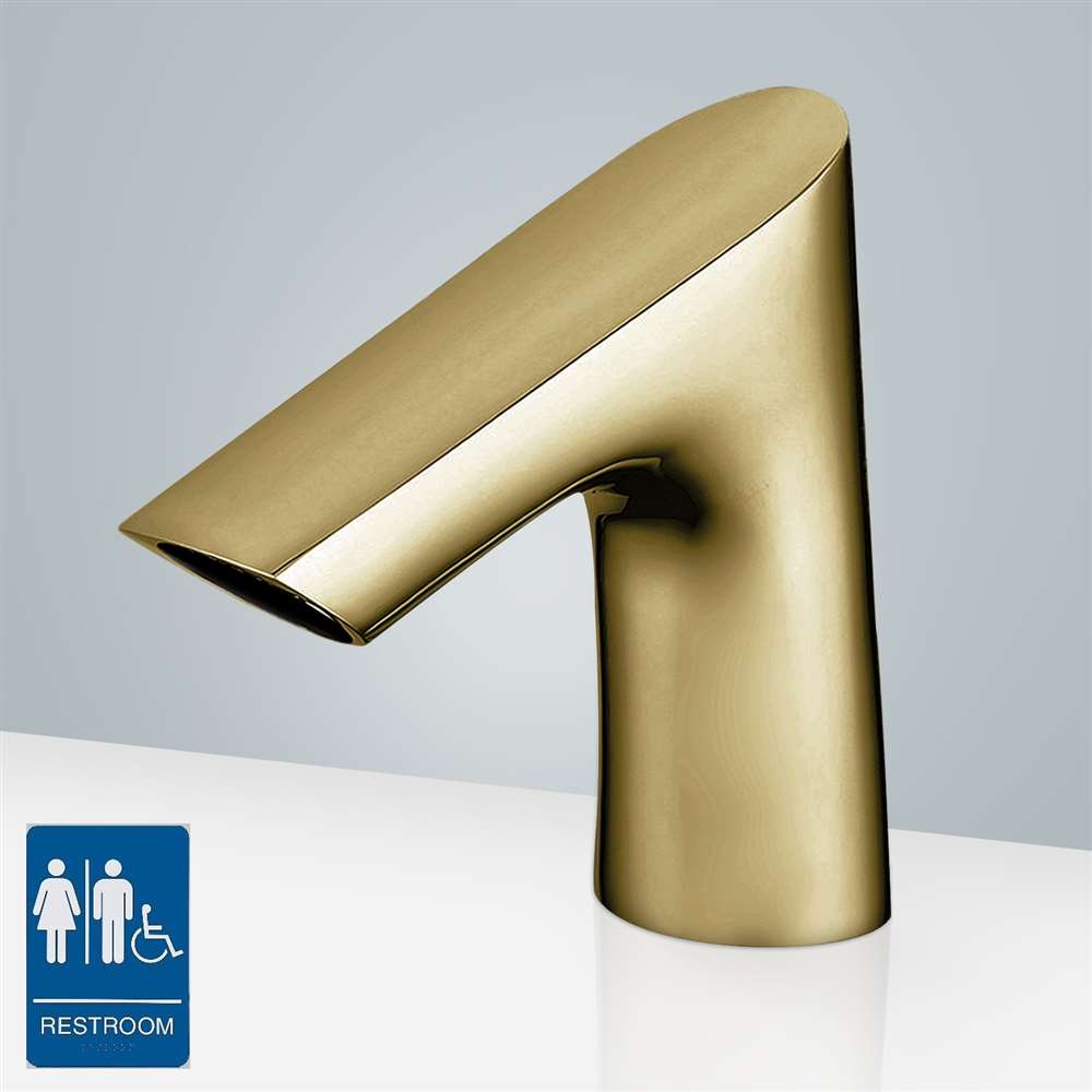
Fontana Commercial Brushed Gold Touchless Automatic Sensor Faucet:
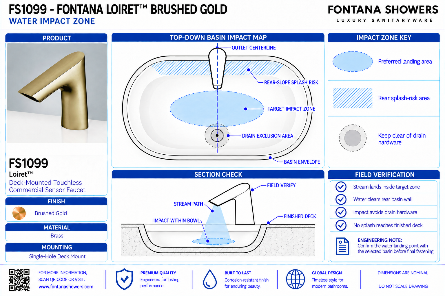
Water Impact Zone
This coordination resource supports architects, plumbing engineers,
interior designers, contractors and facility managers evaluating
the FS1099 discharge within a commercial lavatory basin. The water
impact detail should identify the outlet position, discharge direction,
intended landing area and surrounding splash boundaries. Coordinate
these relationships using the selected basin profile and confirm
performance through an installed water test.
Fontana FS1099 Faucet-to-Basin Discharge Coordination
Evaluate the angled outlet against the actual bowl geometry.
The intended water landing area should remain inside the basin,
with usable space for handwashing and controlled splash at the
rear wall, side walls and front rim. Establish the final mounting
position from confirmed outlet geometry and basin testing.
- Model: FS1099
- Finish: Brushed Gold
- Installation: Single-hole deck mount
- Overall height: 6 inches / 152.4 mm
- Base dimension shown: 1.5 inches / 38.1 mm
- Upper-body dimension shown: 0.5 inch / 12.7 mm
- Published flow rate: 2 GPM / 7.57 L/min
- Inlet / outlet connection: G1/2 inch
- Detection zone: 16–32 cm or adjustable
- Inductive opening time: Less than 1 second
- Inductive closing time: Less than 2 seconds
- Numerical outlet height and spout reach: Not provided in the specification drawing
- Impact-zone verification: Selected basin geometry and installed discharge testing
Required Water Impact Zone Drawing Package
Use a basin section and a coordinated plan to explain discharge
placement. Identify the outlet, finished deck, bowl profile and
proposed impact area. Label an untested stream path as schematic;
a perspective product image does not establish a measured discharge
angle, outlet height or landing distance.
Outlet Reference Position
Locate the discharge opening relative to the finished deck
and basin. Obtain confirmed outlet coordinates from approved
dimensional information or the supplied product before assigning
numerical landing-position dimensions.
Basin Section and Profile
Show the actual bowl depth, rear slope, front rim and drain
location. Use the selected basin’s geometry to assess whether
the proposed discharge path encounters a steep surface or
remains within the intended washing area.
Schematic Discharge Path
Illustrate the proposed stream direction without assigning
an unsupported angle or trajectory. Distinguish the preliminary
coordination path from the stream observed during final
commissioning.
Primary Water Landing Area
Identify an intended impact area inside the bowl and away
from exposed countertop edges. Confirm its suitability through
testing; placement directly over the drain is not a universal
requirement for satisfactory basin performance.
Rear-Wall Splash Boundary
Show the relationship between the stream, rear bowl surface
and backsplash. Evaluate rebound during unobstructed discharge
and normal handwashing, including water escaping onto the
rear deck.
Front-Rim and Side Containment
Identify the front and lateral basin boundaries in plan.
Check whether the stream or hand-deflected water reaches the
rim, neighboring deck surfaces or the user’s approach area
during operation.
Handwashing Interaction Zone
Coordinate usable hand space with the outlet and bowl.
Evaluate splash with hands beneath the stream because
unobstructed discharge alone does not represent normal
handwashing conditions.
Commissioned Impact Map
Record the observed landing area, stream stability and
splash behavior after installation. Identify the tested basin,
faucet orientation and supply conditions so the results can
support review of repeated lavatory stations.
Engineering note:
The FS1099 specification drawing does not establish numerical
spout reach, outlet height, discharge angle or water-impact distance.
Do not derive these values by scaling the product photograph.
Confirm the supplied outlet geometry and test the selected basin
before accepting a final impact-zone layout. Millimeter equivalents
for the illustrated body dimensions are calculated conversions.
Water Impact Zone Verification Sequence
1. Confirm the Basin Geometry
Review the bowl section, rim configuration and mounting area.
Identify surfaces that could redirect discharge toward the
countertop or outside the basin.
2. Establish the Outlet Position
Confirm the actual discharge opening and faucet orientation.
Use a mock-up or the supplied product where missing dimensional
information affects the mounting location.
3. Prepare the Water Supply
Follow the installation guide’s flushing and connection
procedure. Inspect for leaks and confirm that the supply
arrangement is ready for a representative discharge test.
4. Observe Unobstructed Discharge
Activate the faucet and observe the landing position and
stream formation. Check rebound from the bowl surface and
inspect the surrounding deck for escaping water.
5. Test Normal Handwashing
Move hands through the usable washing area and assess
deflected splash, clearance and sensor response. Check the
front rim, side boundaries and rear deck during the test.
6. Record and Resolve
Document the observed impact area and any splash concerns.
Resolve unsatisfactory performance through approved changes
to alignment, basin selection or the specified outlet arrangement,
then repeat the affected checks.
Architectural and MEP Coordination Considerations
Mounting Setback
Coordinate the faucet centerline with the selected basin’s
rear deck and bowl opening. Confirm discharge placement
before releasing the mounting location for fabrication.
Surface Geometry
Evaluate bowl slopes and local features at the landing area.
Impact on a steep wall, raised drain fitting or shallow surface
can change the direction of rebound.
Flow and Supply Conditions
Record measured discharge and relevant supply conditions
during testing. Compare performance with approved operating
requirements rather than treating the published flow figure
as a guaranteed field measurement.
Outlet Condition
Inspect the discharge opening for debris or irregular stream
formation. Follow the manufacturer’s service instructions
before attributing poor splash performance solely to basin
placement.
Sensor and Accessory Interaction
Coordinate nearby dispensers and reflective finishes with
the sensing area. Verify that normal accessory use does not
produce unintended faucet activation or obstruct handwashing.
Repeated Lavatory Stations
Establish an accepted faucet-and-basin arrangement through
a representative test. Check subsequent stations for consistent
mounting position, outlet condition and operating performance.
FontanaShowers Installation and Specification Resources
Professional Engineering and Accessibility References
Project verification:
This resource supports faucet-to-basin coordination and does not
establish a manufacturer-approved stream trajectory or splash rating.
Confirm outlet geometry, basin compatibility and installed discharge
performance before accepting the final water impact arrangement.
|
|
|