Fontana Touchless Faucets™ | Architectural and Engineering Resource
Fontana Commercial Brushed Gold Touchless Automatic Sensor Faucet:
Deck Opening & Clearance
This installation resource supports architects, plumbing engineers,
countertop fabricators, contractors and installers coordinating the
FS1099 mounting penetration. The opening detail should establish the
permitted hole diameter, countertop thickness, mounting centerline
and underside working space. Coordinate the threaded tube, flexible
water pipe and sensor cable with the base seal and fastening assembly
before releasing the countertop for fabrication.
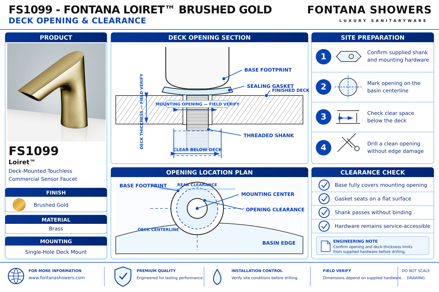
Fontana FS1099 Countertop Penetration and Mounting Clearance
The installation guide provides a mounting-hole range and a
maximum countertop thickness without a deck plate. Coordinate
these limits with the finished countertop assembly and the supplied
hardware. The illustrated faucet base measurement is separate
from the required opening diameter.
- Model: FS1099
- Finish: Brushed Gold
- Installation: Single-hole deck mount
- Mounting-hole diameter: 1.26–1.38 inches / 32–35 mm
- Maximum countertop thickness without deck plate: 1.38 inches / 35 mm
- Overall faucet height: 6 inches / 152.4 mm
- Base dimension shown: 1.5 inches / 38.1 mm
- Upper-body dimension shown: 0.5 inch / 12.7 mm
- Through-deck components: Threaded mounting tube, flexible water pipe and sensor cable
- Base seal: O-ring in the faucet’s bottom groove
- Under-deck fastening: Rubber washer, metal washer, mounting nut and locking screws
- Edge distances and tool clearances: Project-specific; not numerically established in the referenced documents
Required Deck Opening and Clearance Drawing Package
Use a countertop plan and a local mounting section to communicate
the penetration requirements. Dimension the opening from identifiable
basin and deck references. Show the finished countertop assembly,
base contact surface and underside fastening space together, while
distinguishing manufacturer limits from fabricator-selected edge
distances and project service clearances.
Opening Diameter
Identify the permitted mounting-hole range from the installation
guide. Specify the fabrication diameter within that range after
confirming the supplied assembly, and inspect the completed
opening before installation.
Finished Deck Thickness
Show the countertop thickness at the mounting location,
including local build-ups that affect the fastening interface.
Confirm compatibility with the stated limit and the supplied
threaded mounting tube.
Mounting Centerline
Reference the opening centerline to the basin and finished
countertop edges. Coordinate outlet placement using confirmed
faucet geometry before fixing the drilling location.
Base Contact Area
Show the faucet base and sealing interface above the opening.
Confirm that the completed penetration leaves a suitable
contact surface for the supplied base and O-ring without
relying on the base callout as a drilling dimension.
Basin and Edge Separation
Coordinate the penetration with the bowl cutout, rear deck
edge and nearby seams. Obtain material-specific edge-distance
requirements from the countertop fabricator and basin
manufacturer before drilling.
Underside Hardware Envelope
Show the washer assembly, mounting nut and locking screws
beneath the deck. Check their seating and tool access against
basin returns, reinforcement, support brackets and cabinetry.
Hose and Cable Passage
Illustrate the components passing through the single opening.
Keep the water pipe and sensor cable clear of sharp edges,
the base seal and the underside clamping surfaces.
Fabricated Opening Inspection
Record the completed diameter, location and deck thickness.
Inspect edge quality and bearing surfaces, then confirm that
the supplied mounting assembly passes through and seats
correctly before final fastening.
Engineering note:
The FS1099 installation guide lists a mounting-hole diameter of
32–35 mm and a maximum countertop thickness of 35 mm without a deck
plate. These limits do not establish countertop edge distances,
washer-bearing dimensions or minimum tool clearances. Confirm those
requirements using the supplied hardware, basin geometry and
fabricator’s guidance. Do not enlarge the opening beyond the stated
range to resolve routing or fastening conflicts without manufacturer
approval.
Deck Opening and Clearance Verification Sequence
1. Confirm the Mounting Assembly
Review the supplied threaded tube, washers, mounting nut and
routed components. Check that the proposed countertop assembly
accommodates their installation and fastening arrangement.
2. Establish the Opening Location
Coordinate the centerline with the basin, intended washing
position and countertop edges. Check the underside for conflicts
before marking the fabrication drawing.
3. Review Material Constraints
Confirm the fabricator’s drilling method and required separation
from cutouts, seams and edges. Resolve local reinforcement
requirements without obstructing the mounting interface.
4. Fabricate and Inspect
Form the opening to the approved diameter and position.
Inspect for chipping, irregularities or sharp edges that could
affect base seating or damage routed components.
5. Check Assembly Passage
Feed the mounting tube, water pipe and sensor cable through
the opening. Confirm passage without forcing components or
trapping them beneath the base or washer assembly.
6. Verify Seating and Access
Check the above-deck seal, underside washer seating and
fastening-tool approach. Confirm that the completed arrangement
remains accessible for inspection and future removal.
Architectural and MEP Coordination Considerations
Countertop Build-Ups
Account for reinforcing layers and local thickening at the
penetration. Confirm the effective mounting thickness rather
than using the nominal slab dimension alone.
Basin Returns and Supports
Check the opening location against the actual bowl underside
and support system. Preserve a suitable washer-bearing area
and access to the mounting nut and locking screws.
Fabrication Tolerances
Coordinate diameter and positional tolerances with the
fabricator. Keep the completed opening within the manufacturer’s
stated range and document deviations before installation.
Routing Protection
Protect the hose and sensor cable at the penetration.
Coordinate edge treatment with the countertop material and
supplied assembly without restricting component passage.
Above-Deck Working Space
Coordinate the faucet base with the backsplash and adjacent
accessories. Preserve space for positioning, inspection and
routine cleaning around the completed mounting interface.
Accessible Service Arrangement
Evaluate the underside installation together with required
knee and toe clearances. Arrange service components so mounting
access and accessible lavatory space can both be maintained.
FontanaShowers Installation and Specification Resources
Professional Engineering and Accessibility References
Project verification:
This resource supports deck-opening coordination and does not replace
approved countertop fabrication drawings. Confirm the supplied mounting
assembly, finished deck thickness, material-specific edge distances,
basin geometry and service access before drilling and installation.
|
|
|