Fontana Touchless Faucets™ | Architectural and Engineering Resource
Fontana Commercial Brushed Gold Touchless Automatic Sensor Faucet:
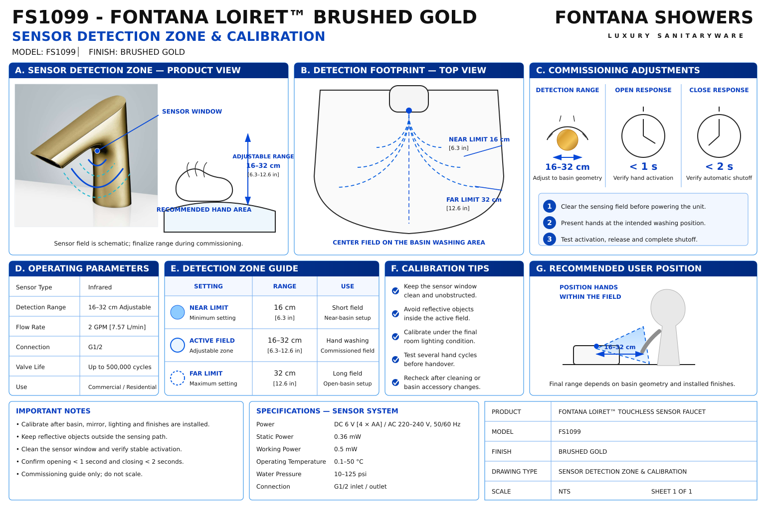
Sensor Detection Zone
This coordination resource supports architects, plumbing engineers,
contractors, commissioning personnel and facility managers evaluating
the FS1099 sensing arrangement within a commercial lavatory assembly.
The detection-zone detail should identify the sensor location, intended
hand approach and surrounding basin surfaces. Coordinate nearby
accessories and reflective finishes, then verify activation and shutoff
with the completed installation.
Fontana FS1099 Infrared Detection and Activation Coordination
Coordinate the sensing area with the normal handwashing position.
The published detection range does not define a fixed cone angle
or guarantee identical response in every basin. Verify the supplied
configuration after the faucet, bowl, lighting and adjacent
accessories are installed.
- Model: FS1099
- Finish: Brushed Gold
- Operation: Infrared touchless sensing
- Published detection zone: 16–32 cm or adjustable
- Inductive opening time: Less than 1 second
- Inductive closing time: Less than 2 seconds
- DC power: 6 V — four AA alkaline batteries
- AC power: 220–240 V, 50/60 Hz
- Overall faucet height: 6 inches / 152.4 mm
- Base dimension shown: 1.5 inches / 38.1 mm
- Upper-body dimension shown: 0.5 inch / 12.7 mm
- Detection angle and field width: Not numerically specified in the referenced documents
- Final detection setting: Verify against the supplied controls and installation procedure
Required Sensor Detection Zone Drawing Package
Use a basin section and coordinated plan to show the sensing
relationship. Identify the sensor window from the supplied product
and illustrate the intended hand approach. Label the detection
envelope as schematic unless its boundaries have been established
through manufacturer information or commissioning measurements.
Keep the sensing area distinct from the water discharge path.
Sensor Location
Identify the sensor window on the actual faucet body.
Reference its position to the outlet and finished deck without
assigning coordinates derived from an unscaled photograph
or an assumed internal arrangement.
Schematic Detection Envelope
Illustrate the intended sensing area beneath or in front
of the sensor according to the supplied configuration.
Do not assign an unsupported cone angle, field width
or uniform detection boundary.
Normal Hand Approach
Show how hands enter the washing area and intersect the
intended sensing path. Check that activation occurs in a
practical position without requiring contact with the
faucet or an awkward approach around the basin rim.
Basin Surface Relationship
Coordinate the sensor with the bowl bottom, rear slope
and raised rim. Test the installed basin for unwanted
activation or missed detection rather than assuming
that the published range establishes basin compatibility.
Adjacent Dispenser Coordination
Show the neighboring dispenser and its normal user approach.
Check whether accessory use or intersecting sensing paths
unintentionally activates either device. Verify operation
with both fixtures installed.
Reflective Finish Review
Identify nearby polished surfaces and mirrors that may
affect the sensing arrangement. Assess response under the
completed lighting conditions and record any required
manufacturer-approved adjustment.
Sensor Cable Connection
Show the sensor cable route to the control equipment.
Preserve connector access and keep the cable clear of
mounting hardware, sharp edges and strain that could
interrupt reliable operation.
Commissioned Detection Boundary
Record observed activation and release positions during
testing. Identify the faucet configuration, basin model
and surrounding conditions so the accepted response
can be checked across repeated lavatory stations.
Engineering note:
The FS1099 specification sheet lists a detection zone of 16–32 cm
or adjustable but does not provide a measured field shape or
detection angle. The installation guide describes automatic
adjustment and references optional remote-control adjustment.
Confirm the adjustment method available with the supplied unit.
Its startup guidance includes different timing references;
follow the applicable manufacturer-confirmed procedure before
evaluating detection performance.
Sensor Detection Zone Verification Sequence
1. Inspect the Sensor Window
Check that the sensing window is clean and unobstructed.
Inspect for damage or material covering the optical surface
before connecting and testing the control system.
2. Confirm Connections and Power
Verify the sensor connection and supplied power configuration.
Check connectors and cable routing before diagnosing
activation concerns as detection-range problems.
3. Complete Startup Adjustment
Follow the applicable installation procedure and keep the
sensing area clear during automatic adjustment. Confirm
startup completion before introducing hands or other
test objects into the field.
4. Test Hand Entry and Withdrawal
Approach from normal user positions and observe activation.
Withdraw hands and verify complete shutoff. Repeat with
different practical hand positions to identify missed
detection or an unnecessarily extended sensing area.
5. Check Unintended Activation
Observe the fixture with the washing area empty, then
operate nearby accessories. Check whether reflections,
dispenser use or movement outside the intended washing
position activates the faucet.
6. Record the Accepted Response
Document the supplied configuration, adjustment method
and observed behavior. Resolve inconsistent response
through manufacturer-approved procedures, then repeat
the affected checks before handover.
Architectural and MEP Coordination Considerations
Basin Geometry
Evaluate the bowl and rim against the actual sensing path.
A raised edge or steep rear surface can change the available
hand approach and the objects presented to the sensor.
Accessory Placement
Coordinate dispenser locations and user movement with the
faucet’s sensing area. Preserve independent operation
and a clear handwashing approach at each fixture.
Lighting and Reflections
Complete response testing under the installed lighting
and finish conditions. Recheck performance after changes
to mirrors, reflective accessories or other nearby surfaces.
Control Access
Maintain access to the sensor connector and control equipment.
Confirm whether adjustment requires automatic calibration,
an optional remote or another supplied control interface.
Accessible User Approach
Evaluate activation from the intended accessible lavatory
approach. Coordinate faucet placement with the complete
fixture arrangement rather than treating detection range
as proof of accessibility compliance.
Operational Maintenance
Include sensor-window inspection and connection checks
in the maintenance procedure. Reassess response after
equipment replacement or changes to the surrounding
lavatory arrangement.
FontanaShowers Installation and Specification Resources
Professional Engineering and Accessibility References
Project verification:
This resource supports sensor coordination and does not establish
a measured detection-field shape or guarantee response in every
installation. Confirm the supplied sensor configuration, startup
procedure and completed lavatory performance before accepting
the final detection arrangement.
|
|
|