Fontana Touchless Faucets™ | Architectural and Engineering Resource
Fontana Commercial Brushed Gold Touchless Automatic Sensor Faucet:
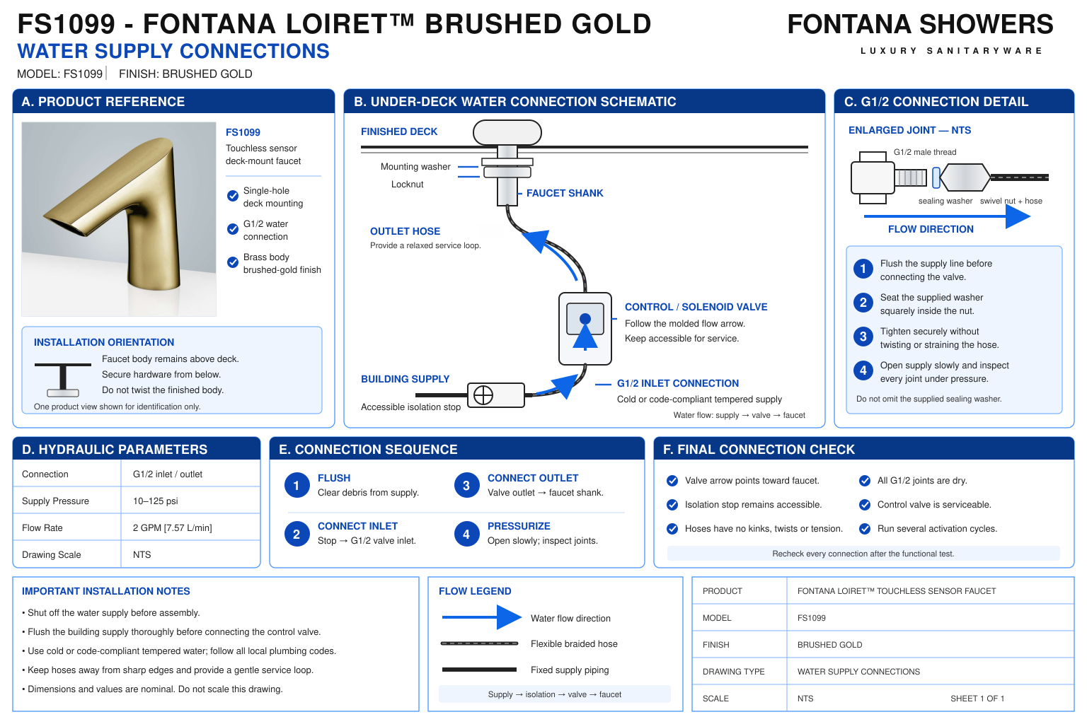
Water Supply Connections
This installation resource supports plumbing engineers, contractors,
installers and facility managers coordinating the FS1099 water supply.
The connection detail should identify the accessible isolation stop,
incoming supply, control-box inlet and outlet, and flexible pipe serving
the faucet. Coordinate connection compatibility, supply flushing,
hose routing and maintenance access before commissioning.

Fontana FS1099 Supply and Control-Box Connections
Connect the incoming water supply to the control-box port marked
“Inlet” and the faucet hose to the port marked “Outlet.”
Confirm these markings on the supplied equipment before assembly.
Keep connections accessible and arrange the flexible pipe without
tension, twisting or interference with the mounting hardware.
- Model: FS1099
- Finish: Brushed Gold
- Installation: Single-hole deck mount
- Listed inlet / outlet connection: G1/2 inch
- Published flow rate: 2 GPM / 7.57 L/min
- Published temperature range: 0.1–50°C
- Incoming supply route: Supply isolation point to control-box inlet
- Faucet supply route: Control-box outlet to faucet hose
- Supply preparation: Flush before connecting to the control assembly
- Temperature arrangement: Confirm the selected single-supply or mixed-water configuration
- Pressure acceptance: Obtain manufacturer clarification of inconsistent pressure entries in the specification sheet
- Service requirement: Accessible isolation fittings and removable connections
Required Water Supply Connection Drawing Package
Use a hydraulic schematic and an under-counter arrangement detail
to communicate the supply path. Label each connection by function
and show flow direction through the control equipment. Identify
connection threads, isolation points, flexible piping and any
project-selected temperature-control components separately.
Incoming Supply and Isolation
Identify the building supply and an accessible service stop.
Coordinate its location with the lavatory supports and
cabinetry so the faucet can be isolated without dismantling
permanent finishes.
Control-Box Inlet
Show the incoming connection at the port marked “Inlet.”
Confirm the supplied port marking, fitting configuration
and flow direction before selecting adapters or completing
the supply connection.
Control-Box Outlet
Trace the outlet connection to the faucet hose.
Keep the inlet and outlet labels visible in the detail,
and arrange the hose so the connection remains accessible
for inspection and removal.
Thread and Seal Interface
Identify compatible mating fittings for the listed G1/2
connection. Confirm whether each joint seals through a washer,
gasket or another specified interface before applying any
thread-sealing material.
Flexible Pipe Routing
Show a practical route between the control equipment and
faucet. Avoid kinks, twisting and contact with sharp edges.
Obtain the hose manufacturer’s bend requirements rather
than assigning an estimated minimum radius.
Selected Temperature Arrangement
Identify whether the installation receives a single supply
or mixed water from a separate temperature-control assembly.
Show optional components only where included in the approved
project configuration.
Flushing and Test Access
Provide a practical means of flushing the supply before
connecting sensitive control components. Preserve access
to inspect joints and observe the complete assembly during
static and operating leak checks.
Service Disconnection Space
Reserve space to operate the isolation fitting and disconnect
the hose connections. Check that maintenance does not require
loading the faucet body, twisting the pipe or disturbing
the mounting assembly.
Engineering note:
The FS1099 documentation lists G1/2 connections. Do not substitute
1/2-inch NPT fittings solely because the nominal sizes appear
equivalent. Verify the actual mating threads and sealing arrangement.
The specification sheet contains inconsistent pressure entries,
including a pressure range labeled “Water Consumption”; obtain
manufacturer clarification before establishing project pressure
limits. Confirm optional mixing components and their separate
operating requirements through the approved submittal.
Water Supply Connection Installation Sequence
1. Confirm the Supply Configuration
Review the selected water-temperature arrangement and supplied
control equipment. Identify the isolation fitting, inlet,
outlet and faucet hose before assembling connections.
2. Isolate and Flush
Prepare the supply in accordance with the installation guide.
Flush into a suitable container before connecting the control
assembly, then isolate the line for connection work.
3. Verify Fittings and Seals
Check mating threads, connection size and supplied sealing
components. Inspect washers and gasket seats, and resolve
incompatible fittings before tightening any joint.
4. Connect Inlet and Outlet
Connect the incoming supply to the designated inlet and
the faucet hose to the designated outlet. Support the
fittings during assembly and avoid transferring tightening
force into the hose or control enclosure.
5. Restore Supply and Inspect
Restore the water supply in a controlled manner.
Inspect all connections before operating the faucet,
then repeat the inspection while water is flowing and
after the valve closes.
6. Verify Operating Performance
Complete startup using the applicable manufacturer procedure.
Check discharge, temperature, shutoff and leakage, and
document the supply conditions used for acceptance.
Architectural and MEP Coordination Considerations
Static and Dynamic Pressure
Evaluate the supply with the fixture closed and operating.
Use manufacturer-confirmed limits and account for project
conditions that affect pressure at the control-box inlet.
Temperature Management
Coordinate the delivered-water temperature with the intended
occupancy and applicable requirements. Verify any selected
mixing device independently; a mixing option alone does
not establish a certified temperature-limiting function.
Flow Verification
Measure installed discharge after flushing and startup.
Investigate supply restrictions, hose deformation or outlet
obstruction where field performance differs from the
approved project requirements.
Equipment Support
Mount the control equipment independently of the flexible
piping. Arrange connections without using the hose to
support enclosure weight or compensate for misaligned
fittings.
Maintenance Isolation
Keep service stops identifiable and reachable.
Provide working space for connection removal and inspection,
including access after cabinetry and lavatory supports
are complete.
Accessible Under-Counter Arrangement
Coordinate piping, control equipment and fittings with
required knee and toe clearances. Address exposed contact
hazards while preserving the service approach.
FontanaShowers Installation and Specification Resources
Professional Engineering and Accessibility References
Project verification:
This resource supports water-supply coordination and does not replace
approved installation submittals. Confirm the supplied connection
threads, sealing components, inlet and outlet markings, operating
limits, temperature-control arrangement and service access before
connection and commissioning.
|
|
|