Fontana Touchless Faucets™ | Architectural and Engineering Resource
Fontana Commercial Brushed Gold Touchless Automatic Sensor Faucet:
Hot & Cold Supply Option
This coordination resource supports plumbing engineers, contractors,
installers and facility managers specifying the FS1099 with an
under-counter mixed-water supply. The connection detail should
distinguish the hot and cold branches, their isolation fittings,
the selected mixing assembly and the downstream sensor-control
equipment. Confirm the supplied configuration before establishing
connection locations, temperature settings and maintenance access.
Fontana FS1099 Optional Under-Counter Mixing Arrangement
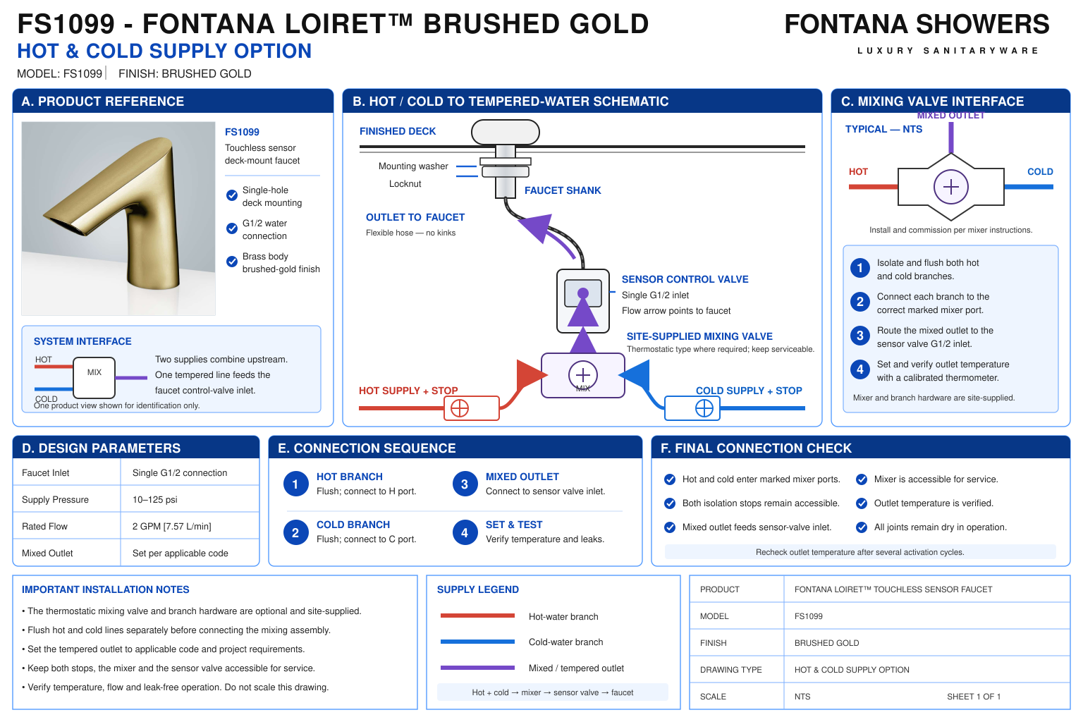
In the mixed-water arrangement, separate hot and cold supplies
feed a selected mixing device before water enters the sensor
control assembly. The faucet’s touchless activation controls
discharge; temperature adjustment depends on the installed
mixing equipment. Confirm whether that equipment is included
in the selected order or specified separately.
- Model: FS1099
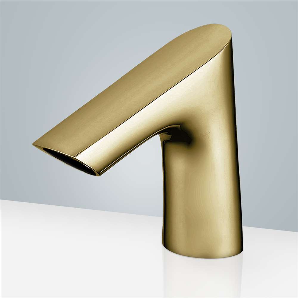
- Finish: Brushed Gold
- Installation: Single-hole deck mount
- Supply option: Separate hot and cold branches serving an under-counter mixing assembly
- Mixed-water route: Mixing outlet to sensor control-box inlet
- Faucet route: Sensor control-box outlet to faucet hose
- Listed faucet inlet / outlet connection: G1/2 inch
- Published faucet flow rate: 2 GPM / 7.57 L/min
- Published faucet temperature range: 0.1–50°C
- Temperature setting: Establish through the selected mixing device and project requirements
- Mixing-device ratings and certification: Verify for the exact submitted device
- Service provision: Accessible hot and cold isolation fittings and mixing controls
Required Hot and Cold Supply Drawing Package
Use a hydraulic schematic and coordinated under-counter layout
to communicate the selected arrangement. Label hot, cold and
mixed-water lines individually, with flow arrows and equipment
boundaries. Identify the mixing device separately from the sensor
control box, and show check valves, strainers or other accessories
only where required by the approved assembly.
Hot Supply Branch
Identify the hot-water connection and accessible isolation
fitting. Coordinate the route to the mixing device’s designated
hot inlet without crossing or obscuring the cold branch
and service controls.
Cold Supply Branch
Identify the cold-water connection and its isolation fitting.
Confirm the mixing device’s inlet markings on the supplied
equipment before connecting the branch or selecting adapters.
Mixing Assembly
Show the exact selected device with its hot inlet, cold inlet
and mixed outlet. Identify adjustment access, support and
required installation orientation using the device-specific
instructions.
Mixed-Water Connection
Trace the mixed outlet to the sensor control-box inlet.
Distinguish temperature management from electronic discharge
control, and identify connection compatibility at each
equipment interface.
Sensor-Control Outlet
Show the control-box outlet connected to the faucet hose.
Preserve the marked flow direction and route the hose
without kinks, tension or interference with the mounting
assembly.
Required Protective Components
Identify check valves, inlet strainers and other components
required by the selected mixing device or approved project
design. Distinguish integral features from separately
installed accessories.
Temperature Verification Point
Identify where delivered-water temperature will be measured
during commissioning. Provide access to the adjustment
mechanism and document the accepted setting under the
specified test conditions.
Isolation and Service Space
Show access to both supply stops, mixing controls and removable
connections. Coordinate component removal with cabinetry,
basin supports and required clearances beneath the lavatory.
Engineering note:
A hot and cold supply option does not by itself establish thermostatic
regulation, automatic temperature limiting or protection against
supply failure. Confirm these functions and any required certification,
including ASSE 1070 where applicable, for the exact selected device.
Do not use the faucet’s published temperature range as a recommended
handwashing setpoint. Resolve inconsistent pressure entries in the
FS1099 documentation and verify the separate operating limits of
the mixing assembly before specification.
Hot and Cold Supply Installation Sequence
1. Confirm the Selected Equipment
Identify the supplied faucet controls and selected mixing
device. Review connection sizes, inlet markings, operating
requirements and the approved temperature-management function.
2. Prepare Both Supply Branches
Isolate the hot and cold supplies and flush each branch
before connecting the equipment. Follow the relevant
installation procedures to keep debris out of valves
and sealing interfaces.
3. Connect the Mixing Inlets
Connect each branch to its designated inlet.
Use compatible fittings and required sealing components,
and install any specified protective accessories in
the correct flow direction.
4. Complete the Mixed-Water Route
Connect the mixing outlet to the sensor control-box inlet
and the control-box outlet to the faucet hose.
Support the equipment independently and retain access
to each connection.
5. Inspect and Set Temperature
Restore the supplies and inspect for leaks before operation.
Follow the mixing-device procedure to establish the required
delivered-water temperature, measuring at the designated
verification point.
6. Verify and Document
Complete the specified operating and protective-function
checks using the device manufacturer’s procedure.
Record delivered temperature, relevant supply conditions,
adjustment settings and any outstanding corrective work.
Architectural and MEP Coordination Considerations
Supply Temperature Conditions
Confirm the available hot and cold inlet temperatures against
the selected device’s requirements. Account for the conditions
needed to achieve and maintain the project’s mixed-water setting.
Pressure Compatibility
Review inlet pressure conditions and any permitted pressure
imbalance for the mixing device. Coordinate its operating
envelope with the faucet controls and project supply.
Minimum Operating Flow
Check that the mixing device can perform its specified function
at the actual faucet discharge. Reassess compatibility if
a different flow-control component is selected.
Intermittent Sensor Operation
Evaluate temperature behavior during repeated short activations
and after idle periods. Include startup discharge in the
commissioning assessment rather than measuring only after
prolonged flow.
Adjustment and Maintenance
Keep temperature controls and service components accessible.
Identify any manufacturer-provided setting protection and
document the procedure for adjustment, inspection and
recommissioning.
Accessible Under-Counter Layout
Coordinate the additional mixing equipment and branch piping
with required knee and toe clearances. Address exposed
contact hazards while preserving isolation and service access.
FontanaShowers Installation and Specification Resources
Professional Engineering and Accessibility References
Project verification:
This resource supports optional mixed-water supply coordination
and does not establish the inclusion, certification or protective
performance of a particular mixing device. Confirm the ordered
configuration, device-specific instructions, operating limits,
delivered-water setting and service access before commissioning.
|
|
|