Fontana Touchless Faucets™ | Architectural and Engineering Resource
Fontana Commercial Brushed Gold Touchless Automatic Sensor Faucet:
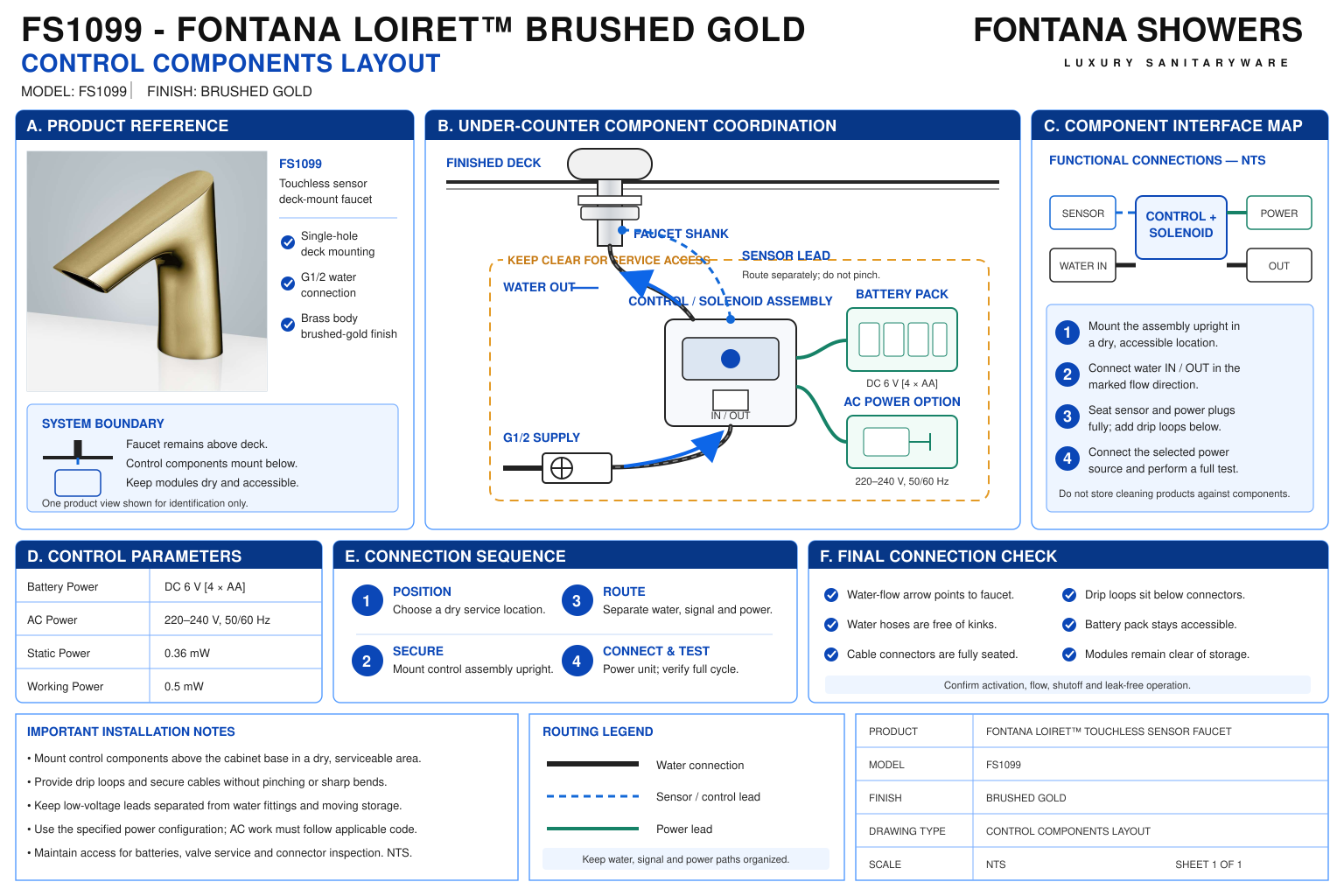
Control Components Layout
This coordination resource supports plumbing engineers, electrical
coordinators, contractors, installers and facility managers arranging
the FS1099 control equipment beneath a commercial lavatory. The layout
should identify the control box, water inlet and outlet, sensor
connection, supplied power components and service approach.
Coordinate these interfaces with the basin, fastening assembly,
cabinetry and accessible clearances before installation.

Fontana FS1099 Under-Counter Control Arrangement
Position the control box where the faucet hose, incoming supply
and sensor cable can connect without strain. Preserve access
to the cover, connectors and serviceable components.
Identify the supplied AC/DC or battery-only configuration
before finalizing the equipment layout.
- Model: FS1099
- Finish: Brushed Gold
- Control equipment location: Accessible under-counter mounting position
- Water inlet: Incoming supply to the port marked “Inlet”
- Water outlet: Port marked “Outlet” to the faucet hose
- Listed inlet / outlet connection: G1/2 inch
- Sensor interface: Faucet sensor cable connected to the control box
- DC power: 6 V — four AA alkaline batteries
- Listed AC power: 220–240 V, 50/60 Hz
- Power configuration: Confirm the supplied control-box variant and equipment labels
- Optional mixing assembly: Coordinate separately where included in the approved supply arrangement
- Service allowance: Cover removal, battery access, connector release and component replacement
Required Control Components Layout Drawing Package
Use an under-counter elevation and a functional connection
schematic to identify each component and its service boundary.
Distinguish water piping from sensor and power wiring.
Reference the supplied equipment for enclosure dimensions,
mounting points, connector positions and orientation.
Label project-selected clearances separately from manufacturer
requirements.
Control-Box Position
Locate the enclosure against the actual basin and cabinet
geometry. Select a position that accommodates the supplied
hose and cable lengths while preserving access for inspection,
cover removal and servicing.
Mounting Surface and Orientation
Identify the mounting substrate and equipment orientation.
Follow the supplied mounting instructions and select fixings
suitable for the actual substrate rather than assuming that
one anchor type suits every installation.
Water Inlet and Outlet
Show the incoming supply and faucet connection at their
designated ports. Include flow arrows and accessible isolation,
with sufficient working space to disconnect fittings without
loading the enclosure or connected hose.
Sensor Connection
Trace the cable from the faucet through the deck to the
control-box connector. Keep the route clear of mounting
hardware and sharp edges, and provide access to release
the connector during maintenance.
Battery Access
Identify the battery compartment or case in the supplied
configuration. Reserve space to open the enclosure and
remove the battery case without disturbing water connections
or permanent cabinet finishes.
AC Power Interface
Where an AC configuration is supplied, identify its approved
power interface and electrical connection location.
Coordinate installation from equipment labels and applicable
electrical requirements; do not infer internal wiring details.
Optional Mixing Equipment
Show a separate mixing device only where selected.
Coordinate its inlet connections, adjustment access and
mixed-water route without obstructing the control-box cover
or sensor connector.
Component Removal Envelope
Identify the space needed to remove the cover, operate
isolation fittings and withdraw serviceable components.
Check the complete removal path against basin supports,
pipework and cabinet openings.
Engineering note:
Confirm the supplied control-box variant before assigning enclosure
dimensions, mounting centers or connector locations.
The FS1099 documentation illustrates more than one power arrangement;
the final layout must match the equipment delivered for the project.
Do not assume an enclosure protection rating, universal power input,
cable extension allowance or minimum service clearance where none
is established by the applicable manufacturer instructions.
Control Components Layout Verification Sequence
1. Identify the Supplied Components
Inventory the control box, faucet hose, sensor connector,
power components and selected accessories. Check equipment
markings against the approved configuration before setting
mounting locations.
2. Check the Available Space
Review the actual basin underside, cabinet opening and
support arrangement. Identify the equipment position and
removal path while maintaining required accessible clearances.
3. Confirm Connection Reach
Check the supplied hose and cable against the proposed
routing. Resolve insufficient reach through approved component
selection or equipment positioning before mounting.
4. Mount and Connect
Secure the equipment in the required orientation using
suitable fixings. Complete the designated water, sensor
and power connections in accordance with the supplied
installation procedure.
5. Verify Service Access
Confirm that the cover, battery case and connectors remain
accessible. Check isolation and fitting access before
cabinet panels or other obstructions are installed.
6. Commission and Record
Complete startup, leak inspection and sensor-operation
checks. Record the installed component configuration,
isolation locations and service approach for facility
maintenance.
Architectural and MEP Coordination Considerations
Independent Equipment Support
Support the enclosure from the mounting substrate.
Do not use the water hose, sensor cable or power connection
to carry equipment weight or hold the control box in position.
Leak Exposure
Coordinate electrical components with potential leakage
points and the equipment’s documented installation limits.
Preserve access to inspect water joints without disturbing
electrical connections.
Cover and Fastener Access
Account for the tool approach to enclosure screws and the
movement needed to remove the cover. Check access with
the final basin, piping and cabinet panels in place.
Routing and Connector Protection
Arrange service slack without leaving cables or hoses
vulnerable to snagging. Avoid tension at connectors and
interference with doors, drawers or removable access panels.
Component Identification
Keep equipment labels and inlet/outlet markings readable.
Identify isolation and power provisions so maintenance
personnel can service the correct assembly at multi-station
lavatories.
Accessible Lavatory Clearance
Coordinate the control box and connected services with
required knee and toe space. Address exposed contact
hazards while retaining a practical maintenance approach.
FontanaShowers Installation and Specification Resources
Professional Engineering and Accessibility References
Project verification:
This resource supports control-equipment coordination and does not
replace approved installation submittals or electrical instructions.
Confirm the supplied enclosure, mounting arrangement, power interface,
connection locations and service requirements before installation
and commissioning.
|
|
|