Fontana Touchless Faucets™ | Architectural and Engineering Resource
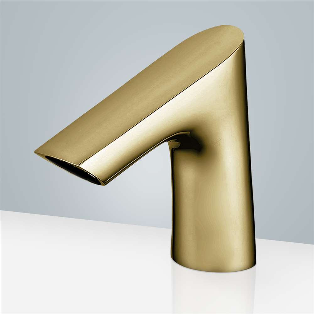
Fontana Commercial Brushed Gold Touchless Automatic Sensor Faucet:
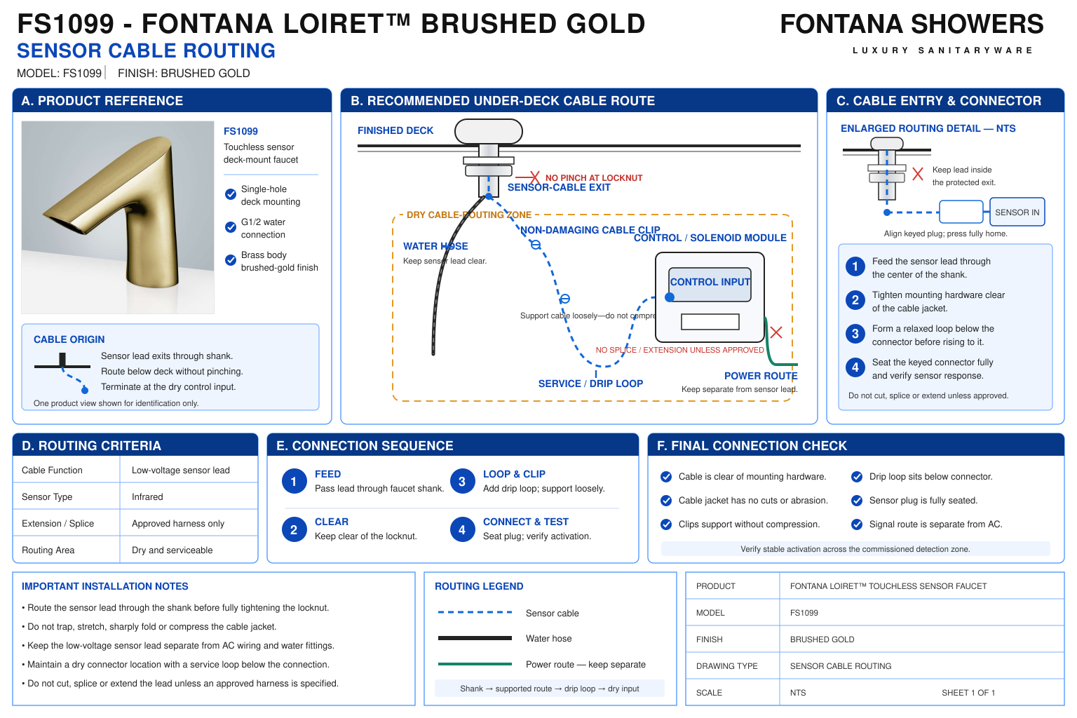
Sensor Cable Routing
This coordination resource supports plumbing engineers, electrical
coordinators, contractors, installers and facility managers arranging
the FS1099 sensor connection beneath a commercial lavatory. The routing
detail should trace the cable from the faucet through the deck opening
to the control box. Coordinate the route with mounting hardware, water
connections and cabinetry while preserving connector access and
sufficient slack for servicing.
Fontana FS1099 Sensor Cable and Control-Box Interface
Route the faucet’s sensor cable through the mounting opening
and connect it to the designated control-box interface.
Keep the cable clear of the base seal and underside clamping
surfaces. Locate the control equipment within the supplied
cable’s usable reach, allowing access for connection and removal.
- Model: FS1099
- Finish: Brushed Gold
- Installation: Single-hole deck mount
- Cable origin: Faucet sensor assembly
- Through-deck route: Shared mounting opening with the mounting tube and flexible water pipe
- Connection destination: Designated sensor interface on the control box
- Routing priority: Protection from pinching, abrasion, twisting and connector strain
- Service provision: Accessible connector and practical disconnection slack
- Cable length and minimum bend radius: Confirm for the supplied assembly
- Extension compatibility: Obtain manufacturer approval before extending or modifying the cable
- Enclosure and connector protection ratings: Verify from the supplied equipment documentation
- Final check: Sensor operation after fastening and completion of the surrounding installation
Required Sensor Cable Routing Drawing Package
Use a local mounting section and an under-counter routing elevation.
Identify the cable passage, fastening assembly, control-box connector
and service access. Distinguish the sensor lead from water piping
and mains wiring. Reference the actual supplied cable and connector
rather than assigning an estimated length, pinout or extension limit.
Faucet Cable Exit
Show the cable leaving the faucet assembly and entering
the deck penetration. Preserve its natural route without
forcing it against the mounting tube, hose connection
or underside of the faucet base.
Deck Penetration Passage
Illustrate the sensor cable passing through the single
mounting opening alongside the other installation components.
Check that the connector can pass without forcing it
through an undersized or obstructed space.
Base and Washer Clearance
Keep the cable outside the O-ring contact area and the
underside washer-bearing surfaces. Show clearance from
the mounting nut and locking screws so fastening cannot
trap or compress the lead.
Protected Under-Counter Route
Trace the cable around basin returns, support brackets
and cabinet edges. Avoid abrasion points and locations
where stored items or maintenance activity could snag
the cable.
Control-Box Connector
Identify the designated sensor connection on the supplied
equipment. Show connector alignment and access without
assuming a particular locking mechanism, pin arrangement
or sealing method.
Service Slack and Support
Provide enough slack to disconnect the sensor lead without
pulling on the faucet or control box. Position suitable
supports so the cable remains orderly without being
tightly compressed.
Power and Piping Interfaces
Identify nearby electrical and hydraulic services.
Keep the sensor lead clear of hot surfaces, moving components
and water-connection work, and coordinate any required wiring
separation through the applicable electrical design.
Completed Route Inspection
Inspect the entire accessible route after fastening and
cabinet completion. Verify connector seating, cable condition
and freedom from tension before completing sensor startup
and operating checks.
Engineering note:
The FS1099 installation guide identifies the sensor cable connection
to the control box but does not establish a universal cable length,
minimum bend radius, connector pinout or permitted extension distance.
Confirm these details for the supplied assembly. Do not splice,
shorten or substitute the sensor lead without manufacturer approval.
Do not assume that the sensor connector has the same protection
rating or electrical function as the power interface.
Sensor Cable Routing Installation Sequence
1. Inspect the Cable Assembly
Check the lead and connector for visible damage.
Identify the correct control-box interface and review
the supplied connection procedure before routing.
2. Confirm the Equipment Position
Check usable cable reach against the proposed control-box
location. Allow for the actual route and servicing rather
than relying on the straight-line distance between components.
3. Feed Through the Deck
Guide the cable and connector through the mounting opening
with the other components. Protect the connector from
impact and keep the lead clear of the base sealing surface.
4. Complete Faucet Fastening
Keep the cable outside the washer, nut and screw contact
areas while securing the faucet. Reinspect the route
after tightening to confirm that the lead has not been trapped.
5. Route and Connect
Arrange the lead along the protected route and connect it
using the supplied interface instructions. Handle the
connector body rather than pulling on the cable, and retain
access for future disconnection.
6. Verify Sensor Operation
Follow the applicable startup procedure and test normal
activation and release. Inspect the completed route again
after access panels and surrounding components are fitted.
Architectural and MEP Coordination Considerations
Actual Routing Length
Account for bends, supports and connection access when
locating the control box. Resolve insufficient cable reach
through approved equipment positioning or manufacturer-approved
components.
Penetration Edge Condition
Inspect the deck opening and nearby cabinet penetrations
for sharp edges. Coordinate suitable protection without
restricting component passage or interfering with
the mounting assembly.
Connector Accessibility
Keep the sensor interface reachable after the basin and
cabinetry are installed. Provide working space to inspect
and release the connector without moving water fittings.
Moving Cabinet Components
Check the cable route against drawers, hinges and removable
panels. Verify their complete movement so the lead cannot
become pinched, pulled or caught during normal use.
Maintenance Identification
Distinguish the sensor lead from power connections and
neighboring fixture cables. Maintain readable identification
where multiple controls share an under-counter service area.
Accessible Under-Counter Space
Secure loose routing outside the required knee and toe
clearances. Coordinate protection from snagging and contact
while retaining a practical service approach.
FontanaShowers Installation and Specification Resources
Professional Engineering and Accessibility References
Project verification:
This resource supports sensor cable coordination and does not
authorize cable modification or establish connector protection
ratings. Confirm the supplied lead, control interface, routing
requirements and startup procedure before installation and
commissioning.
|
|
|