Fontana Touchless Faucets™ | Architectural and Engineering Resource
Fontana Commercial Brushed Gold Touchless Automatic Sensor Faucet:
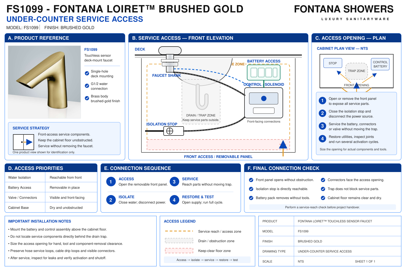
Under-Counter Service Access
This coordination resource supports architects, plumbing engineers,
contractors, installers and facility managers planning maintenance
access beneath the FS1099 lavatory installation. The access layout
should identify supply isolation, control-box servicing, battery
replacement, connector release and faucet-fastening access.
Coordinate these tasks with the basin, supports and cabinetry
before permanent finishes restrict the working area.

Fontana FS1099 Maintenance and Component Removal Access
Arrange the under-counter equipment so personnel can isolate
the water supply, reach connections and remove serviceable
components. Evaluate the complete working approach, including
cover movement, tool positioning and component withdrawal,
rather than relying only on visibility through a cabinet opening.
- Model: FS1099
- Finish: Brushed Gold
- Installation: Single-hole deck mount
- Water isolation: Accessible service stop or selected hot and cold isolation fittings
- Control-box access: Cover screws, cover removal and serviceable components
- Battery access: Battery case and its cover where supplied
- Sensor access: Reachable cable connector with disconnection slack
- Water connections: Accessible inlet, outlet and faucet-hose fittings
- Mounting access: Under-deck washers, mounting nut and locking screws
- Optional mixing device: Adjustment, isolation and removal access where installed
- Electrical servicing: Access appropriate to the supplied power configuration
- Access dimensions: Establish from the actual equipment and demonstrated maintenance tasks
Required Under-Counter Service Access Drawing Package
Use an under-counter elevation, a local section and an access-panel
detail to communicate the maintenance arrangement. Show the installed
equipment, tool approach and component removal paths. Distinguish
the clear cabinet opening from the unobstructed space available
behind it, and label project-selected service dimensions separately
from manufacturer requirements.
Service Opening
Locate the cabinet opening or removable panel relative to
the equipment. Show its clear dimensions after accounting
for frames, hinges and fixed fittings, and confirm that
personnel can reach the intended service points.
Water Isolation Access
Identify each isolation fitting and the space needed to
operate it. Keep stops reachable with the control equipment
and cabinet panels in their final positions.
Control-Box Cover Removal
Show the approach to the cover screws and the movement
required to remove the cover. Check clearance from the
bowl underside, supply fittings, supports and adjacent
equipment.
Battery Replacement Path
Where a battery case is supplied, identify its release
and withdrawal path. Allow access to the case cover
without pulling on connected wiring or disturbing
water connections.
Sensor Connector Release
Locate the sensor interface and preserve space to handle
the connector body. Provide practical slack for disconnection
while keeping the lead protected from cabinet movement
and fastening hardware.
Water Fitting Disconnection
Show working access around inlet, outlet and hose connections.
Allow the fittings to be supported during removal so
maintenance does not twist the flexible pipe or load
the control enclosure.
Faucet Fastening Access
Identify the mounting nut and locking screws beneath
the deck. Check the tool approach for releasing the faucet
when base-seal replacement or complete fixture removal
is required.
Equipment Withdrawal Route
Trace the removal path for the control box and selected
accessories. Verify that the equipment can pass through
the service opening after disconnection without removing
permanent countertop or wall finishes.
Engineering note:
The referenced FS1099 documents do not establish a universal
access-panel size or minimum maintenance envelope. Determine
service dimensions from the supplied equipment, connector
operation, tool approach and component removal paths.
Access sufficient to install equipment may not be sufficient
to maintain it. Verify the arrangement before closing cabinetry
or installing permanent obstructions.
Service Access Verification Sequence
1. Identify Maintenance Tasks
List the tasks associated with the supplied configuration:
isolation, battery replacement, connector release, fitting
disconnection and component removal. Include optional
equipment only where installed.
2. Review the Completed Geometry
Check the actual basin underside, support brackets and
cabinetry. Account for hinges, panel frames and neighboring
services that reduce the usable working space.
3. Demonstrate Isolation Access
Confirm that the relevant water stops can be reached and
operated. Identify the applicable power-isolation procedure
for the supplied equipment before service work begins.
4. Check Tools and Removal Paths
Verify access to screws, nuts and connectors with appropriate
tools. Demonstrate the necessary cover and component movement
without forcing hoses or cables aside.
5. Confirm Restoration Access
Check that components can be reinstalled and connections
inspected through the same opening. Preserve visibility
for leak checks and access for startup verification
after servicing.
6. Record the Service Arrangement
Document panel locations, isolation points and component
identification. Provide the accepted access arrangement
and relevant maintenance instructions at handover.
Architectural and MEP Coordination Considerations
Panel Construction
Coordinate removable panels and their fasteners with
the maintenance approach. Ensure panel removal does not
require disturbing the faucet, countertop or connected
equipment.
Equipment Position
Locate service points toward the accessible working area
where the supplied routing permits. Avoid placing cover
screws or connectors directly behind fixed supports
or inaccessible basin returns.
Hose and Cable Slack
Provide practical movement for disconnection without
leaving loose loops vulnerable to snagging. Keep service
slack clear of drawers, hinges and component withdrawal
paths.
Leak Inspection
Preserve a view of water connections during maintenance
and recommissioning. Coordinate access so joints can
be inspected after supplies are restored and the faucet
is operated.
Shared Service Areas
Identify each faucet’s control box and isolation fittings
where multiple stations share a cabinet. Arrange equipment
so servicing one station does not obstruct access
to neighboring assemblies.
Accessible Lavatory Clearances
Keep equipment and panel construction coordinated with
required knee and toe space. Address exposed contact
hazards while preserving the necessary maintenance
approach.
FontanaShowers Installation and Specification Resources
Professional Engineering and Accessibility References
Project verification:
This resource supports maintenance-access coordination and does
not establish manufacturer-approved service dimensions.
Confirm the supplied components, isolation procedures, tool
requirements and removal paths before accepting the completed
under-counter installation.
|
|
|