Fontana Touchless Faucets™ | Architectural and Engineering Resource
Fontana Commercial Brushed Gold Touchless Automatic Sensor Faucet:
BIM / MEP Coordination
This coordination resource supports architects, plumbing engineers,
electrical designers, BIM coordinators, contractors and facility
managers integrating the FS1099 into a commercial lavatory assembly.
The coordinated model should identify the faucet, basin, deck
penetration, water supply, sensor controls and selected power
arrangement. Include installation interfaces and service space
alongside the visible fixture geometry.

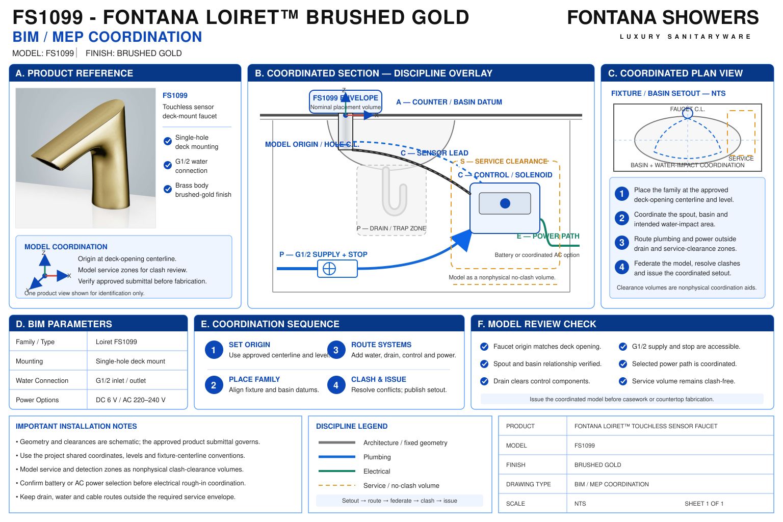
Fontana FS1099 Coordinated Fixture and Services Assembly
Coordinate the visible faucet with its under-counter equipment
and project connections. Validate model geometry and parameters
against the approved submittal, identifying provisional information
where dimensions or equipment details remain unresolved.
Confirm the availability and suitability of any model-specific
BIM file before project use.
- Model: FS1099
- Finish: Brushed Gold
- Installation: Single-hole deck mount
- Overall height: 6 inches / 152.4 mm
- Base dimension shown: 1.5 inches / 38.1 mm
- Upper-body dimension shown: 0.5 inch / 12.7 mm
- Listed inlet / outlet connection: G1/2 inch
- Published flow rate: 2 GPM / 7.57 L/min
- DC power: 6 V — four AA alkaline batteries
- Listed AC power: 220–240 V, 50/60 Hz
- Numerical spout reach and outlet height: Not provided in the specification drawing
- Equipment geometry: Confirm the supplied control-box and accessory configuration
- Model reference: Approved project submittal and applicable manufacturer documents
Required BIM and MEP Coordination Package
Establish the fixture’s placement reference, equipment boundaries
and connection ownership before coordinating services. Use the
project’s agreed information requirements to determine modeling
detail. Keep confirmed dimensions, schematic representations
and maintenance clearances distinguishable in views, schedules
and exported coordination files.
Fixture Placement and Datums
Locate the faucet relative to the finished deck and basin
centerline. Coordinate countertop elevation and fixture
orientation using consistent project datums, avoiding
conflicting placement references between disciplines.
Basin and Deck Interface
Coordinate the mounting penetration with the selected basin,
countertop thickness and underside supports. Review the
opening and fastening arrangement before issuing fabrication
information.
Water Supply Connections
Identify the incoming supply, isolation fittings and control-box
inlet. Trace the outlet connection to the faucet, and verify
the relationship between the listed connection designation
and project piping adapters.
Power Configuration
Identify the supplied battery-only or AC/DC arrangement.
Coordinate any required electrical provision from approved
equipment information, distinguishing the external supply
interface from the sensor connection.
Control and Sensor Routing
Locate the control equipment within the usable reach of
the supplied hose and sensor cable. Coordinate routing
around basin returns, supports and cabinet movement without
assigning unsupported cable-extension limits.
Optional Mixing Assembly
Include a mixing device only where selected for the project.
Identify its separate hot, cold and mixed-water interfaces,
operating requirements and adjustment access using approved
device-specific information.
Service and Removal Space
Represent access for isolation, cover removal, battery
replacement, connector release and faucet fastening.
Check removal paths as well as physical collisions with
neighboring components.
Fixture Data and Schedules
Coordinate model identification, finish, selected options
and connection information with the fixture schedule.
Record document references and unresolved parameters
so provisional data is not mistaken for approved information.
Engineering note:
A BIM resource link does not establish the availability, accuracy
or completeness of a model-specific FS1099 file. Validate any
downloaded or project-created model against the approved submittal.
Do not derive missing spout reach, outlet height or service dimensions
by scaling a photograph. The illustrated body dimensions do not
define a complete fabrication model; their millimeter equivalents
above are calculated conversions.
BIM and MEP Coordination Sequence
1. Establish Approved Inputs
Identify the selected faucet, basin, control equipment
and accessories. Collect the applicable submittals and
mark missing dimensions or conflicting information
for resolution.
2. Validate the Model
Check units, placement references, orientation and available
geometry. Confirm that modeled dimensions and equipment
variants match the selected assembly before connecting
project services.
3. Coordinate Discipline Interfaces
Assign responsibility for the deck penetration, water
supply, electrical provision and optional mixing equipment.
Align model parameters and schedules with those agreed
interfaces.
4. Review Conflicts and Access
Check the assembly against the basin, structure and cabinetry.
Include fastening access, equipment servicing and accessible
lavatory clearances in addition to physical collision checks.
5. Resolve Coordination Issues
Assign each issue to a responsible discipline and document
its resolution. Update affected views, schedules and
fabrication references together when equipment positions
or connection arrangements change.
6. Verify the Installed Arrangement
Compare the completed installation with the accepted layout.
Record approved field changes and retain component
identification, connection locations and maintenance
information for handover.
Architectural and MEP Coordination Considerations
Geometry and Information Status
Distinguish approved product geometry from schematic
equipment representations. Identify the purpose and
limitations of each model element before using it
for fabrication or installation.
Hydraulic Design Data
Keep published outlet flow separate from the project’s
calculated system demand. Resolve inconsistent pressure
entries in the faucet documentation before establishing
operating limits in schedules or model parameters.
Electrical Interface Ownership
Confirm the supplied equipment ratings and installation
method before assigning an electrical connection.
Do not infer a universal input voltage or direct mains
connection from a generic model parameter.
Countertop Fabrication Release
Coordinate the mounting location and penetration with
the approved basin and hardware. Confirm fabrication
dimensions independently of visual alignment in
the architectural model.
Accessible Lavatory Assembly
Evaluate approach, faucet access and required knee and
toe clearances with the full under-counter arrangement.
Include control equipment, supports and piping in
the accessibility review.
Asset and Maintenance Information
Retain useful equipment identification, selected options
and service references in the handover record.
Avoid filling unsupported parameters with estimated
values merely to complete the model.
FontanaShowers Installation and Specification Resources
Professional Engineering and Accessibility References
Project verification:
This resource supports multidisciplinary coordination and does not
constitute an approved BIM model or fabrication drawing.
Confirm geometry, connection interfaces, selected equipment,
service clearances and information status against approved project
documentation before construction.
|
|
|