Fontana Chrome Wall-Mounted Sensor Faucets™ | Architectural and Engineering Resource
Chrome Wall Mount Sensor Faucets:
Dimensions and Planning Guide
This dimensions and planning guide is intended to support architects,
plumbing engineers, interior designers, contractors, installers,
specifiers and facility managers coordinating Fontana chrome wall-mounted
automatic sensor faucets across commercial, hospitality, healthcare,
institutional and public washroom projects. The guide addresses product
projection, wall rough-in planning, spout reach, basin alignment, mounting
height, service clearances, sensor positioning and dimensional review
across the available faucet configurations within this category.
Fontana Chrome Wall-Mounted Automatic Sensor Faucets
This category includes multiple chrome wall-mounted automatic
sensor faucet configurations intended for hands-free lavatory
operation. Product dimensions, spout profiles, wall flanges,
concealed valve assemblies, sensor positions and connection
requirements may vary according to the selected faucet model.
This page should be used as a category-level planning resource
rather than as a universal dimensional specification. Final wall
openings, mounting positions, concealed clearances, water
connections, electrical requirements and service locations must be
verified using the approved documentation for the selected model.
-
Category:
Chrome wall-mounted automatic sensor faucets
-
Installation:
Wall mounted
-
Operation:
Infrared touchless activation
-
Finish:
Chrome
-
Applications:
Commercial, hospitality, healthcare, institutional and public lavatories
-
Dimensions:
Model specific
-
Wall rough-in:
Verify from the selected model documentation
-
Water configuration:
Varies according to model and project requirements
-
Power configuration:
AC, battery or model-specific arrangement
-
Service access:
Required for concealed operating components
Required Dimensions and Planning Package
Each category-level planning drawing should use a consistent scale,
dimension style, finished-wall reference and product-identification
method. The drawings should distinguish general planning principles
from model-specific measurements and direct the project team to verify
all final dimensions using the selected faucet’s approved documentation.
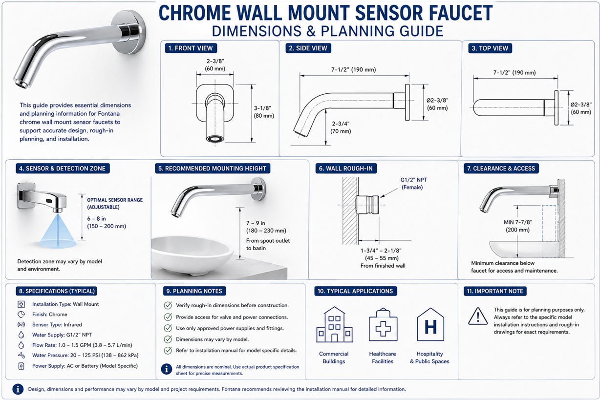
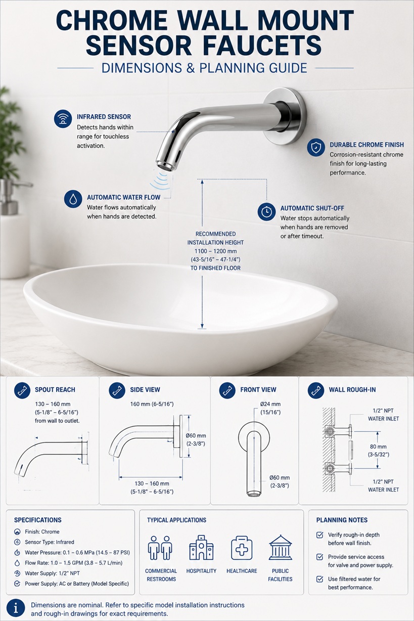
Dimensions and Planning Guide
Provides an overall planning framework for chrome wall-mounted
sensor faucets, including wall projection, mounting height,
basin coordination, rough-in preparation and concealed service
access.
Product Size Comparison
Compares the principal dimensional characteristics of the
available faucet configurations, including spout profile,
projection, flange size and concealed component requirements.
Overall Dimensions
Identifies the dimensional categories that should be reviewed
for each selected model, including width, height, projection
and visible wall-mounted components.
Wall Projection
Defines the distance from the finished-wall surface to the
faucet outlet. This measurement should be coordinated with the
basin depth, rear rim and intended stream landing area.
Spout Reach Planning
Reviews the horizontal reach required to direct the water stream
into the usable basin area without discharging onto the rear
ledge, countertop or front rim.
Wall-Flange Coordination
Identifies the exposed flange footprint and its relationship
to tile joints, stone panels, mirrors, backsplashes and adjacent
washroom accessories.
Finished-Wall Reference
Establishes the completed wall surface as the principal reference
for faucet projection, flange seating and concealed rough-in
depth.
Wall Rough-In Planning
Coordinates wall openings, concealed connections, internal
support, wiring routes and operating components before tile,
stone or permanent wall finishes are installed.
Mounting Support
Identifies the need for suitable backing, blocking or structural
support within the wall assembly according to the selected
faucet configuration and mounting method.
Mounting Height
Establishes the vertical relationship between the faucet
centerline, finished countertop, basin rim and usable
handwashing area.
Basin Alignment
Coordinates the faucet centerline and outlet with the selected
basin so the water stream enters the intended capture area and
supports comfortable hands-free use.
Water Stream Landing
Identifies the intended water-impact area within the basin and
should be reviewed together with bowl depth, drain location and
splash-control requirements.
Sensor Positioning
Reviews the relationship between the infrared sensor, hand
position, basin profile and nearby reflective surfaces that may
influence touchless activation.
Operating Clearance
Defines the unobstructed area required around the faucet outlet
and sensor field for natural hand movement and reliable
automatic operation.
Adjacent Fixture Spacing
Coordinates spacing between faucets, soap dispensers, mirrors,
hand dryers and other accessories so sensor fields and user
zones do not interfere with one another.
Concealed Component Zone
Identifies the wall or cabinet area required for valves,
control boxes, transformers, battery packs, hoses and other
model-specific operating components.
Service Access Planning
Preserves access to concealed plumbing, electrical and control
components for inspection, adjustment and replacement without
removing permanent finishes.
Accessibility Planning
Coordinates faucet placement, activation area and basin
relationship with applicable accessible reach, approach and
lavatory-clearance requirements.
Model Verification
Confirms that the selected faucet’s actual dimensions, wall
openings, power requirements, connection arrangement and
service zones have been reviewed before construction.
Engineering note:
Category-level planning drawings do not establish universal dimensions
for every faucet within the category. Final wall projection, spout
reach, mounting height, wall openings, concealed clearances, sensor
position, connections and power requirements must be verified using
the approved specification sheet and installation instructions for the
selected faucet model.
Category Planning Workflow
Select the Faucet
Choose the wall-mounted sensor faucet according to design
profile, projection, sensor arrangement, power source and
project application.
Review Documentation
Obtain the selected model’s specification sheet, installation
instructions, dimension drawing and available project-submittal
information.
Coordinate the Basin
Confirm that the spout projection and outlet are compatible
with the basin depth, rear ledge and intended stream landing
point.
Establish Wall References
Set the finished-wall line, faucet centerline, mounting height
and rough-in depth before framing and concealed services are
finalized.
Coordinate Services
Review supply piping, valves, controllers, power components
and service access with the plumbing and electrical drawings.
Check Sensor Clearance
Confirm that the basin, backsplash, mirror and adjacent
accessories do not obstruct the intended infrared detection
field.
Preserve Service Access
Maintain practical access to all concealed operating components
without requiring removal of tile, stone or permanent wall
panels.
Complete Verification
Confirm final dimensions, wall conditions, basin alignment,
clearances, connections and accessibility requirements before
installation.
Architectural and MEP Coordination
Wall Construction
Coordinate framing, blocking, waterproofing, tile, stone,
wall panels and other finish materials affecting the final
mounting depth.
Plumbing Coordination
Confirm supply routing, shutoff locations, valve orientation,
pressure conditions and service access for the selected faucet.
Electrical Coordination
Coordinate transformers, battery packs, receptacles, control
boxes and cable routes according to the selected model’s power
configuration.
Basin Compatibility
Verify that the selected basin geometry is compatible with the
faucet projection, outlet position and sensor location.
Finish Coordination
Coordinate the chrome finish with mirrors, dispensers,
accessories and surrounding materials while maintaining
practical cleaning access.
Multi-Faucet Layout
In shared washbasins, maintain consistent centerlines,
projection and fixture spacing while preventing overlapping
sensor zones.
Chrome Wall-Mounted Faucet Resources
Professional Planning References
Project verification:
This category-level dimensions and planning guide does not replace
model-specific specifications, installation instructions or approved
project submittals. The architect, plumbing engineer, electrical engineer,
interior designer, contractor and licensed installer should verify the
selected faucet model, final dimensions, finished-wall construction,
mounting support, rough-in depth, spout projection, basin alignment,
sensor position, power requirements, service access, accessibility
criteria and locally adopted codes before construction or installation.
|
|
|