Fontana Automatic Sensor Faucets™ | Architectural and Engineering Resource
Fontana American Standard Deck-Mounted Sensor Faucet:
Electrical Control Diagram
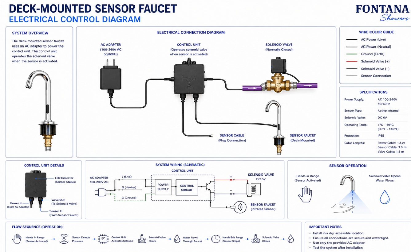
This electrical control diagram resource is intended to support architects,
electrical engineers, plumbing engineers, contractors, installers and
facility managers coordinating the Fontana American Standard deck-mounted
automatic sensor faucet. The drawing package identifies the infrared
sensor, sensor cable, control box, AC transformer or battery power
supply, solenoid valve, electrical routing, low-voltage connections,
automatic shutoff signal and commissioning sequence required for reliable
touchless operation.
Fontana American Standard Deck-Mounted Sensor Faucet
The electrical control system manages automatic faucet operation
through communication between the infrared sensor, electronic
control module and solenoid valve. The system activates water flow
when a valid sensor signal is received and automatically closes the
solenoid after the user leaves the detection area.
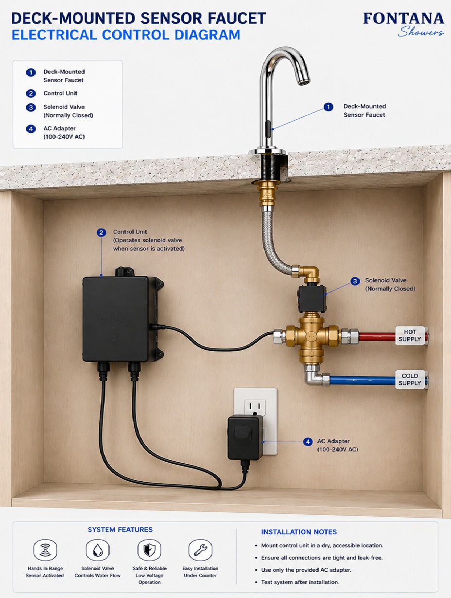
The electrical diagram should be used for coordination of power
supply routing, controller location, low-voltage cable management,
solenoid wiring and commissioning. Final electrical requirements
should always be confirmed using the approved FontanaShowers
specification sheet and installation instructions.
- Model: FS2361TFDP
- Installation: Deck mounted
- Sensor: Infrared touchless activation
- Controller: Electronic control box
- Power: AC adapter or battery configuration (model dependent)
- Output: Low-voltage solenoid control
- Cable type: Factory electrical harness
- Application: Commercial and residential lavatories
Required Electrical Control Diagram Package
Each electrical drawing should use a consistent symbol set, cable
identification, wiring references and product identification block.
The diagram should distinguish power input, sensor communication,
controller functions, solenoid output and service-access locations.
Electrical Control Diagram
Shows the complete electrical relationship between the power
supply, infrared sensor, control box, solenoid valve and faucet.
Power Supply
Identifies the incoming electrical source supplying the faucet
control system. The installation may use an AC transformer or
model-approved battery pack depending on the selected
configuration.
Battery Pack
Illustrates the optional battery power arrangement used on
battery-operated models and identifies the service-access
location for replacement.
AC Transformer
Shows the low-voltage transformer supplying the controller.
The transformer location should remain accessible for future
inspection and replacement.
Control Box
Identifies the electronic controller responsible for processing
sensor signals and operating the solenoid valve.
Infrared Sensor Input
Shows the communication path between the infrared sensor and
the controller. The sensor cable should remain protected from
damage and moisture.
Sensor Cable
Illustrates the low-voltage cable routing between the faucet
body and electronic controller while avoiding sharp bends or
compression.
Solenoid Output
Shows the electrical connection from the controller to the
solenoid valve responsible for automatic water flow control.
Cable Routing
Defines the recommended routing path for all electrical cables
within the cabinet while maintaining separation from plumbing
lines and moving components.
Moisture Protection
Identifies areas requiring protection from water exposure,
condensation and cleaning chemicals to maintain long-term
electrical reliability.
Automatic Shutoff Signal
Shows the electrical signal generated when the user leaves the
sensor field, instructing the controller to close the solenoid
and stop water flow.
Commissioning Verification
Illustrates the final electrical testing sequence confirming
power availability, sensor communication, controller response
and solenoid operation.
Engineering note:
Electrical control diagrams are coordination documents only and
should not replace the approved FontanaShowers wiring diagram,
installation instructions or project electrical documentation.
Verify voltage, polarity, cable routing, controller configuration,
power source, grounding requirements and local electrical codes
before energizing the system.
Project verification:
The architect, electrical engineer, plumbing engineer, contractor and
licensed installer should verify the final power supply, controller
location, cable routing, sensor wiring, solenoid connection, moisture
protection, commissioning procedure and locally adopted electrical
requirements before placing the automatic sensor faucet into service.
|
|
|