Fontana Automatic Sensor Faucets™ | Architectural and Engineering Resource
Fontana American Standard Deck-Mounted Sensor Faucet:
Exploded Assembly and Parts Identification
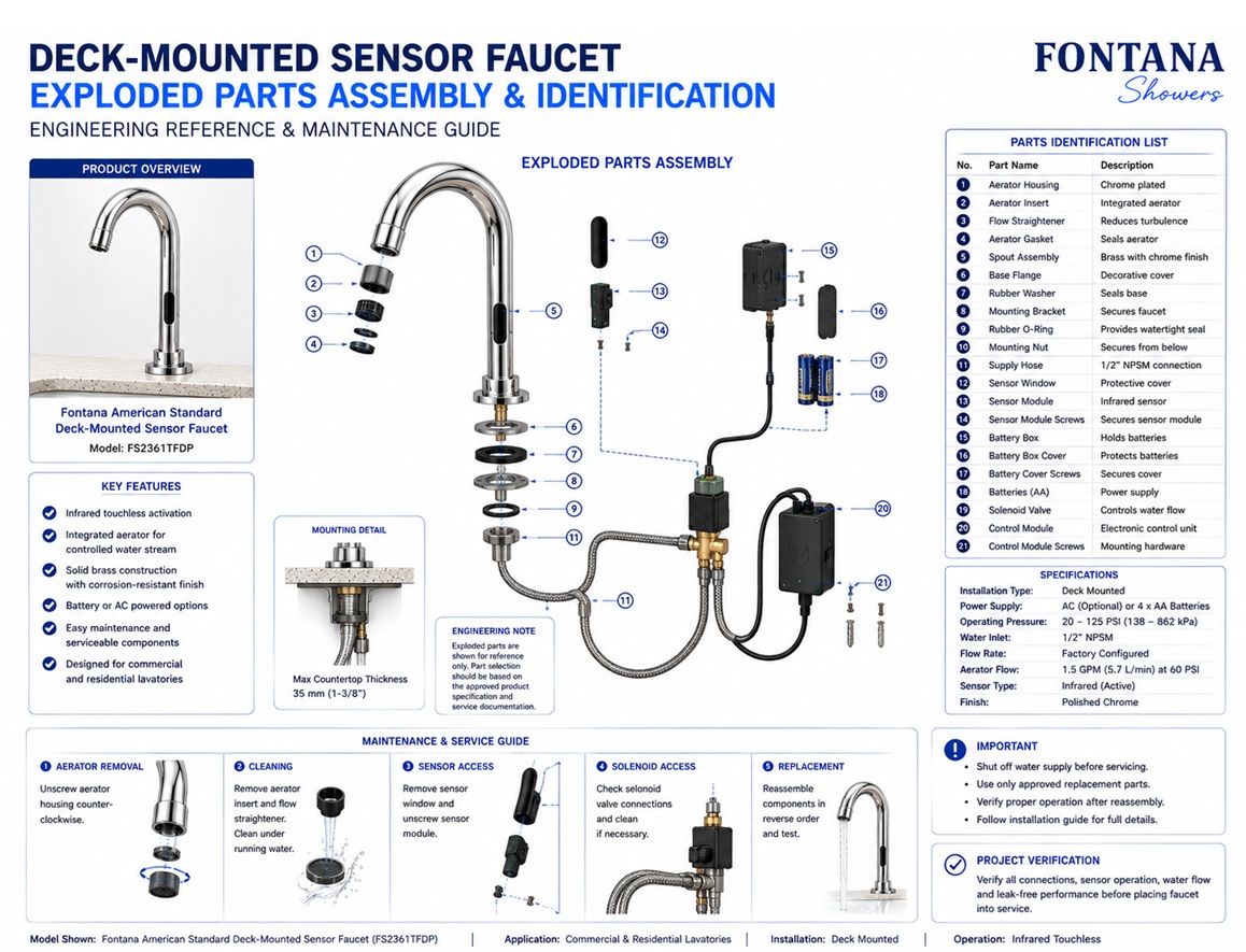
This exploded assembly and parts-identification resource is intended to
support architects, plumbing engineers, maintenance personnel,
contractors, installers and facility managers coordinating the Fontana
American Standard deck-mounted automatic sensor faucet. The drawing
package identifies the faucet body, spout assembly, infrared sensor,
aerator, mounting hardware, flexible supply hose, solenoid valve,
electronic control box, power supply, electrical harness and other
serviceable components used during installation, inspection and future
maintenance.
Fontana American Standard Deck-Mounted Sensor Faucet
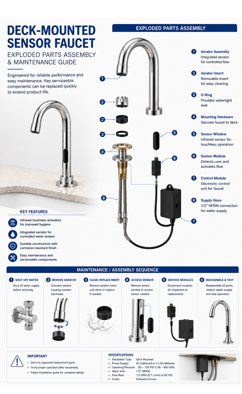
The exploded assembly drawing illustrates the relationship between
individual mechanical and electrical components before final
assembly. It helps installers understand component orientation,
assembly order, maintenance access and replacement procedures
without disassembling the complete faucet.
The drawing should be used during installation planning,
troubleshooting and service operations. Final replacement parts
and assembly procedures should always be confirmed using the
current FontanaShowers specification sheet and approved service
documentation.
- Model: FS2361TFDP
- Installation: Deck mounted
- Construction: Solid brass faucet body
- Sensor: Infrared touchless activation
- Control: Electronic control module
- Flow Control: Solenoid-operated valve
- Service: Replaceable maintenance components
Required Exploded Assembly Drawing Package
Each exploded drawing should use a consistent item-number system,
component callouts and product-identification block. Every removable
part should be clearly identified while preserving the correct
assembly sequence from the faucet body to the concealed operating
components.
Exploded Assembly Overview
Shows the complete faucet separated into individual components
while preserving their original assembly order.
Faucet Body
Identifies the primary brass casting supporting the sensor,
spout and internal water passage.
Spout Assembly
Illustrates the outlet section together with the internal
connection to the faucet body.
Infrared Sensor Module
Shows the sensor assembly responsible for detecting user hand
movement and initiating automatic operation.
Aerator Assembly
Identifies the removable outlet component responsible for water
stream conditioning and flow regulation.
Mounting Shank
Shows the threaded section used to secure the faucet to the
countertop or sink deck.
Rubber Gasket
Illustrates the sealing gasket positioned between the faucet
base and finished countertop.
Mounting Washer
Identifies the washer used to distribute clamping force during
faucet installation.
Lock Nut
Shows the retaining nut securing the faucet assembly beneath
the countertop.
Flexible Supply Hose
Illustrates the flexible connection between the faucet body
and the solenoid assembly.
Solenoid Valve
Identifies the electronically operated valve controlling water
flow during automatic operation.
Control Box
Shows the electronic controller processing sensor input and
operating the solenoid valve.
Power Supply
Illustrates the AC transformer or battery assembly supplying
power to the controller.
Electrical Harness
Shows the factory cable assembly interconnecting the sensor,
controller and solenoid valve.
Replacement Parts Identification
Provides item numbers for serviceable components to simplify
future replacement and maintenance operations.
Assembly Sequence
Illustrates the recommended order for assembling the faucet
from the countertop upward and beneath the deck.
Serviceable Components
Identifies components that may be inspected, cleaned or
replaced during scheduled maintenance.
Maintenance Inspection
Shows the principal inspection points for routine servicing
and preventive maintenance.
Commissioning Verification
Confirms correct assembly, secure connections, electrical
operation and water-flow performance before the faucet is
placed into service.
Engineering note:
The exploded assembly drawing is a coordination and service reference
and should not replace the approved FontanaShowers service manual,
installation instructions or replacement-parts documentation. Verify
component compatibility, assembly procedures and replacement parts
before maintenance or repair.
Project verification:
The architect, plumbing engineer, maintenance supervisor, contractor
and licensed installer should verify the final assembly sequence,
component identification, replacement parts, electrical connections,
water connections and commissioning procedures using the approved
FontanaShowers documentation before returning the faucet to service.