Fontana Automatic Sensor Faucets™ | Architectural and Engineering Resource
Fontana American Standard Deck-Mounted Sensor Faucet:
Sensor Detection Zone
This sensor detection-zone resource is intended to support architects,
plumbing engineers, electrical engineers, interior designers, contractors,
installers and facility managers coordinating the Fontana American Standard
deck-mounted automatic sensor faucet within commercial, hospitality,
healthcare, institutional, public and residential lavatory environments.
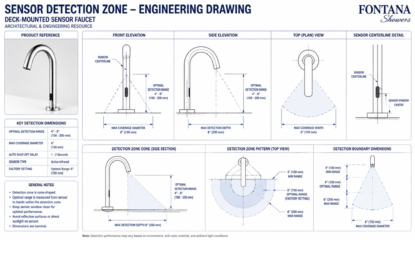
The technical drawing identifies the infrared sensor position, hand-entry
area, activation field, user approach direction, basin relationship,
reflective-surface considerations and the clear zone required for reliable
hands-free operation.
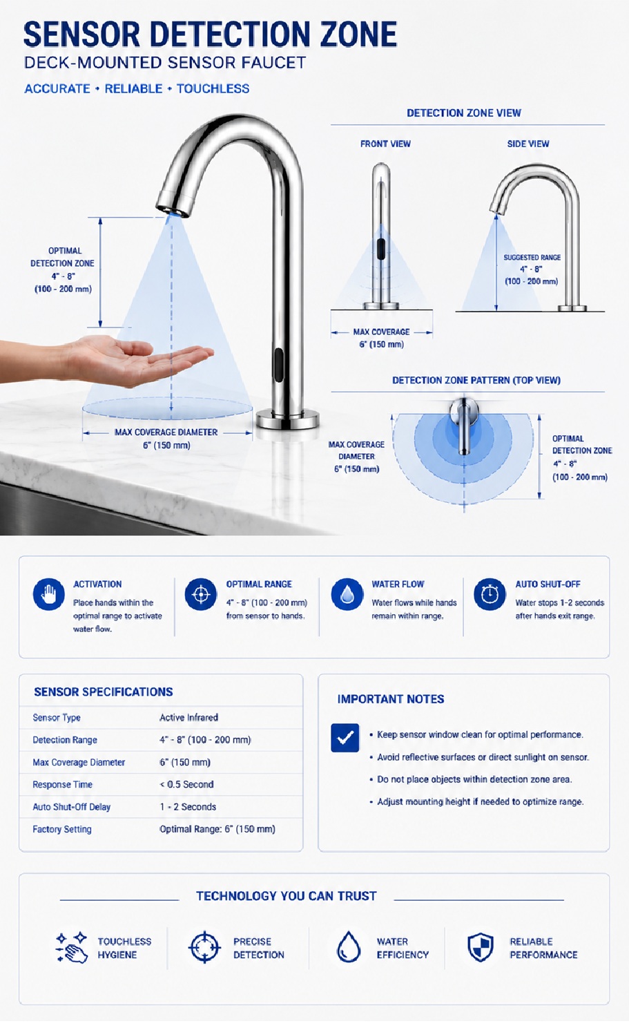
Fontana American Standard Deck-Mounted Sensor Faucet
The Fontana American Standard Sensor Faucet uses infrared touchless
activation to initiate water flow when a user’s hands enter the
approved sensing area. Reliable operation depends on the relationship
between the sensor window, hand position, faucet outlet, basin profile
and surrounding reflective surfaces.
The detection-zone drawing should be reviewed during fixture
selection, basin coordination and commissioning. Final sensor
response, activation distance and operating behavior must be
verified using the current product specification, installation
instructions and approved project submittal.
-
Model:
FS2361TFDP
-
Installation:
Deck mounted
-
Mounting configuration:
Single hole
-
Finish:
Polished chrome
-
Material:
Brass
-
Faucet type:
Automatic motion-sensor sink faucet
-
Sensor type:
Infrared touchless activation
-
Sensor position:
Integrated within the faucet body
-
Detection range:
Verify from current product documentation
-
Activation direction:
User hand entry beneath the outlet area
-
Automatic shutoff:
Model-specific sensor-controlled operation
-
Working pressure:
0.05–0.8 MPa
-
Application:
Commercial and residential lavatories
Required Sensor Detection-Zone Drawing Package
Each detection-zone drawing should use a consistent scale, dimension
style and product-identification block. References should be taken from
the infrared sensor window, faucet centerline, aerator outlet, finished
countertop and basin edge. The drawing should distinguish the intended
hand-activation field from surrounding surfaces or objects that may
interfere with reliable sensor response.
Sensor Detection Zone
Shows the complete activation field beneath and forward of the
faucet sensor. The drawing identifies the intended hand-entry
area, user approach direction, faucet outlet, basin relationship
and surrounding clearance required for reliable touchless
operation.
Infrared Sensor Position
Identifies the sensor window within the faucet body and its
relationship with the aerator outlet, finished countertop and
basin. The sensor face should remain visible and unobstructed
throughout normal use.
Hand Activation Area
Defines the intended space where the user places hands to
activate water flow. The activation area should align naturally
with the handwashing zone while remaining clear of the basin
rim and backsplash.
User Approach Direction
Shows the direction from which the user’s hands enter the
detection field. The approach path should be unobstructed by
soap dispensers, shelves, accessories or projecting countertop
features.
Activation Distance
Identifies the model-specific distance between the infrared
sensor and the intended hand-detection area. The final range
should be verified from the current product documentation and
confirmed during commissioning.
Detection Field Angle
Illustrates the directional spread of the infrared sensing
field relative to the faucet body and countertop. The field
should cover the intended user interaction area without
extending unnecessarily toward adjacent fixtures.
Basin Rim Clearance
Shows the clear relationship between the sensor field and the
basin rim. Projecting or highly reflective rims should not
occupy the active sensing area or trigger unintended operation.
Backsplash Clearance
Identifies the spacing between the faucet, sensor field and
backsplash. Reflective stone, polished tile, glass or metal
surfaces should be reviewed for possible interference with
sensor response.
Reflective Surface Zone
Highlights nearby polished or mirrored surfaces that may reflect
infrared energy toward the sensor. Fixture placement and sensor
commissioning should account for the basin finish, backsplash,
mirror and adjacent metallic accessories.
Adjacent Fixture Clearance
Shows the separation required between the sensor field and
adjacent faucets, soap dispensers or accessories. Each fixture
should operate independently without overlapping activation
zones.
False Activation Risk
Identifies conditions that may cause unintended water flow,
including reflective surfaces, objects left within the sensing
field, moving accessories or incorrect sensor alignment.
Automatic Shutoff Zone
Explains that water flow should stop after the user’s hands
leave the detection area. Shutoff response should be confirmed
during commissioning in accordance with the selected product
configuration.
Engineering note:
Do not establish the sensor range or detection-field limits from an
illustration alone. Final activation distance, detection angle,
response timing and automatic shutoff behavior should be verified
using the current FontanaShowers specification sheet, installation
instructions and approved project submittal, then confirmed under
actual site conditions during commissioning.
Sensor Performance Considerations
Hand Position
Users should be able to place their hands naturally beneath
the outlet and within the detection field without contacting
the faucet body or basin.
Sensor Visibility
Keep the sensor window free from soap residue, mineral deposits,
dust and cleaning-product film that may reduce detection
reliability.
Basin Geometry
Coordinate the sensor field with basin depth, rear ledge,
rim profile and bowl geometry so fixed surfaces do not occupy
the active sensing zone.
Reflective Finishes
Review polished chrome, stainless steel, glass, stone and
glazed surfaces near the faucet for reflections that may affect
sensor performance.
Ambient Lighting
Consider strong direct sunlight, intense task lighting or
unusual infrared sources when locating and commissioning the
faucet sensor.
Fixture Spacing
Maintain suitable spacing between multiple sensor faucets so
their activation fields do not interfere with one another or
create unintended operation.
Cleaning Conditions
Remove cleaning cloths, tools, containers and maintenance
materials from the sensing field before evaluating faucet
operation.
Commissioning Test
Test activation and shutoff from multiple hand positions after
installation, then confirm that nearby surfaces do not cause
false or delayed response.
Architectural and User Coordination
Accessible Hand Reach
Coordinate the sensor activation area with the accessible
lavatory layout so users can reach the detection field without
excessive forward reach or contact with surrounding surfaces.
Water Stream Alignment
Position the hand-detection zone and water outlet so activation
occurs over the basin’s usable capture area rather than over
the countertop or front rim.
Soap Dispenser Spacing
Place adjacent soap dispensers outside the active sensing field
and allow users to move naturally between soap and water
without unintended faucet activation.
Mirror and Backsplash
Review the mirror, backsplash and wall finishes for reflections
or projections that may influence sensor response or reduce
user clearance.
Multi-Faucet Layout
In shared washbasins, coordinate the spacing and orientation
of each faucet so detection zones remain distinct and aligned
with individual user positions.
Maintenance Access
Preserve access to the sensor face, control components and
power source so performance can be checked, cleaned and
adjusted during routine maintenance.
Sensor Detection and Technical Resources
American Standard Sensor Faucet Product Page
Product information, technical specifications, available
documentation and operating details for the Fontana American
Standard automatic sensor faucet.
Sensor Faucet Installation Guide
Installation, sensor setup, testing, commissioning, cleaning
and maintenance guidance for commercial automatic faucets.
Touchless Sensor Technology
Review infrared sensing principles, touchless activation and
operational considerations for automatic restroom fixtures.
Automatic Sensor Faucet Collection
Explore related deck-mounted, wall-mounted and commercial
automatic sensor faucet configurations and finish options.
Sensor Faucet BIM Files
BIM and architectural coordination resources supporting
sensor-faucet planning, documentation and multidisciplinary
project development.
Sensor Faucet Setup Resource
General guidance covering automatic operation, sensor response,
power supply, commissioning and maintenance.
Professional Engineering and Accessibility References
Project verification:
Sensor detection-zone drawings are coordination tools and do not replace
approved product specifications, installation instructions or project
submittals. The architect, engineer, contractor and licensed installer
should verify the final sensor position, activation distance, detection
field, faucet orientation, basin profile, reflective surfaces, adjacent
fixture spacing, accessible hand reach, power condition, response timing,
automatic shutoff and locally adopted requirements before final
commissioning.
|
|
|