Fontana Touchless Faucet & Vessel Sink Systems™ |
Architectural and Engineering Resource
Fontana DSFD0024GS Vessel Sink and Chrome Touchless Sensor Faucet:
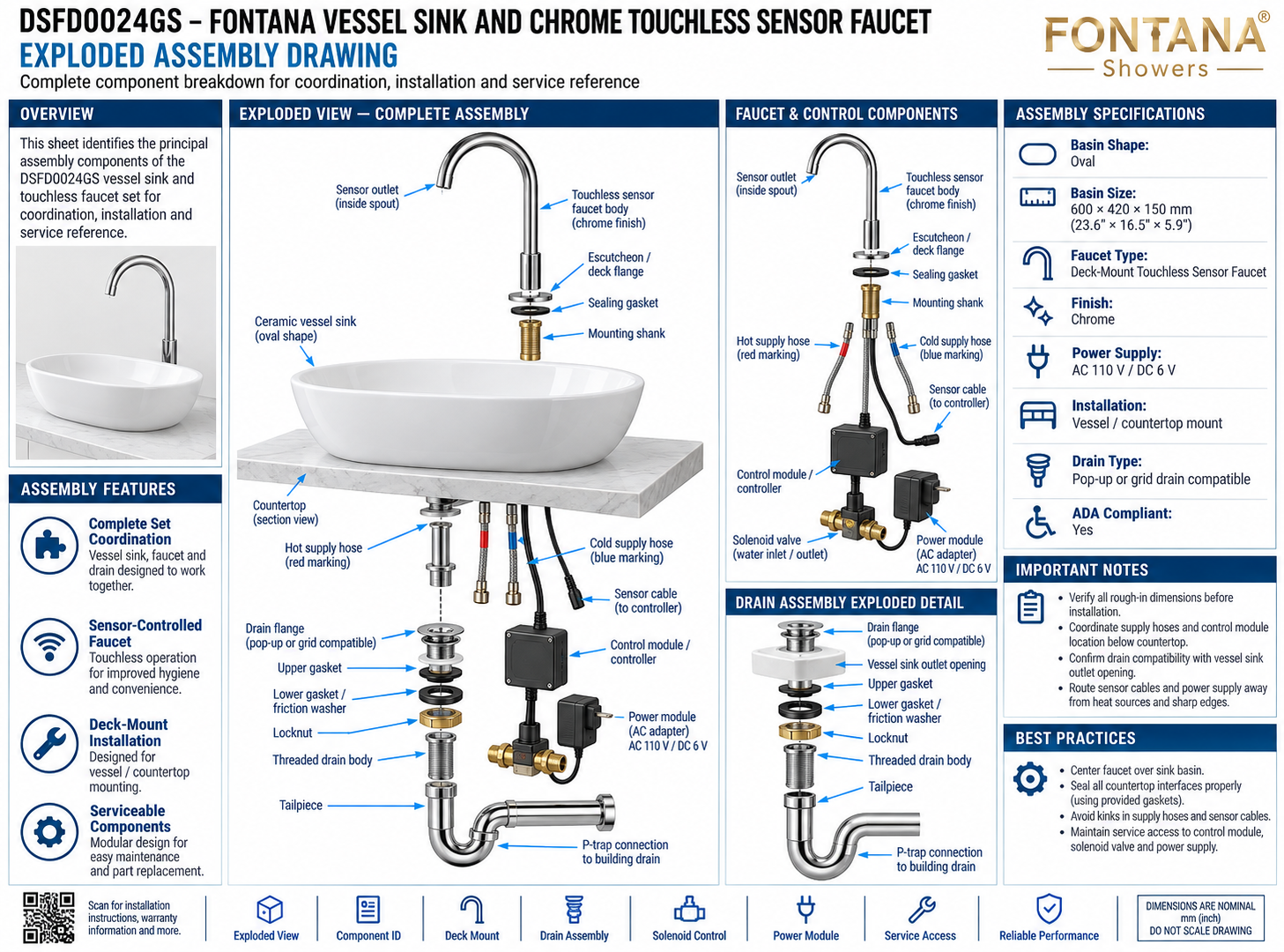
Exploded Assembly Drawing
This exploded-assembly resource is intended to support architects,
plumbing engineers, contractors, installers, service technicians and
facility personnel coordinating the Fontana DSFD0024GS vessel sink and
chrome touchless sensor faucet combination. The drawing package identifies
the principal faucet, basin, mounting, supply, sensor, controller,
solenoid, power, drain and trap components required for installation,
service coordination and future component replacement.
Fontana DSFD0024GS Complete Faucet, Basin & Control Assembly
The DSFD0024GS is illustrated as a modular vessel-sink and
touchless-faucet system composed of the chrome sensor faucet,
deck-mount hardware, ceramic basin, hot and cold supply hoses,
sensor cable, electronic controller, solenoid valve, power module,
drain assembly, tailpiece and P-trap connection. The exploded
format allows each serviceable component to be identified and
coordinated before installation.
-
Model:
DSFD0024GS
-
Basin shape:
Oval
-
Basin size:
600 × 420 × 150 mm
(23.6 × 16.5 × 5.9 in.)
-
Faucet type:
Deck-mount touchless sensor faucet
-
Finish:
Chrome
-
Power supply:
AC 110 V / DC 6 V
-
Installation:
Vessel / countertop mount
-
Drain type:
Pop-up or grid drain compatible
-
Sensor system:
Integrated touchless sensor with controller
-
Water control:
Electronic solenoid valve
-
Supply arrangement:
Separate hot and cold flexible hoses
-
Waste connection:
Drain body, tailpiece and P-trap
-
ADA compliant:
Yes
Required Exploded Assembly Drawing Package
Each assembly-coordination drawing should clearly identify the faucet
body, sensor outlet, deck flange, sealing gasket, mounting shank,
vessel basin, hot and cold supply hoses, sensor cable, controller,
solenoid valve, power module, drain flange, gaskets, locknut,
threaded drain body, tailpiece and P-trap connection. Components
should remain identifiable and serviceable after final installation.
Exploded Assembly Drawing
Provides the complete component breakdown of the DSFD0024GS
vessel sink, touchless faucet, electronic controls, water
supplies and drain assembly.
Exploded View — Complete Assembly
Shows the faucet, mounting hardware, ceramic vessel sink,
countertop interface, supply hoses, control module, power
system and drain components arranged in installation order.
Touchless Faucet Assembly
Identifies the chrome faucet body, sensor outlet, escutcheon,
sealing gasket and mounting shank used to secure the faucet
through the countertop.
Hot & Cold Supply Hoses
Shows separate flexible supply hoses identified with red
and blue markings for hot and cold water connection.
Sensor Cable & Controller
Shows the sensor lead connecting the touchless faucet to the
electronic control module responsible for processing the
activation signal.
Solenoid Valve & Power Module
Identifies the electronic solenoid valve that controls water
flow and the AC 110 V / DC 6 V power module supporting the
touchless control system.
Drain Assembly Exploded Detail
Shows the drain flange, vessel outlet opening, upper gasket,
lower gasket / friction washer, locknut, threaded drain body
and tailpiece.
Tailpiece & P-Trap Connection
Illustrates the waste connection from the threaded drain
body through the vertical tailpiece and P-trap to the
building drainage system.
Serviceable Component Layout
Coordinates the modular controller, solenoid, power module,
supply hoses and drain components so they remain accessible
for inspection, maintenance and replacement.
Engineering note:
All component positions and dimensions shown are nominal coordination
references. Final faucet mounting, basin location, supply-hose routing,
controller placement, solenoid configuration, power arrangement,
drain compatibility, gasket sequence and trap connection should be
verified against the actual Fontana DSFD0024GS components and
approved installation documentation before final installation.
Faucet & Deck-Mount Assembly Components
Touchless Faucet Body
The chrome faucet body contains the touchless sensing
components and provides the primary water-delivery path
above the countertop.
Sensor Outlet
The sensor is positioned within the spout area and detects
user hand presence for hands-free faucet activation.
Escutcheon / Deck Flange
The chrome escutcheon forms the visible finished transition
between the faucet body and countertop surface.
Sealing Gasket
The sealing gasket sits beneath the deck flange to help
protect the countertop penetration from moisture.
Mounting Shank
The mounting shank extends through the countertop and
provides the primary mechanical connection securing the
faucet to the deck.
Deck-Mount Coordination
Verify the faucet penetration, countertop thickness,
vessel position and mounting clearances before tightening
the faucet assembly.
Faucet Water-Supply & Control Components
Hot Supply Hose
The flexible hot-water hose is identified with red marking
and routes from the building supply toward the touchless
control assembly.
Cold Supply Hose
The flexible cold-water hose is identified with blue marking
and connects the cold supply to the control system.
Sensor Cable
The sensor cable transfers the faucet's touchless activation
signal to the electronic controller below the countertop.
Control Module
The controller processes the sensor signal and commands
the solenoid valve during faucet operation.
Solenoid Valve
The solenoid valve electronically opens and closes the water
path according to the controller signal.
Power Module
The power module supports the illustrated AC 110 V / DC 6 V
control configuration and should remain accessible and
protected from direct water exposure.
Drain Assembly & Waste Connection Components
Drain Flange
The drain flange installs at the vessel sink outlet and
is shown as compatible with a pop-up or grid-style drain.
Upper Gasket
The upper gasket forms part of the watertight interface
between the drain flange and vessel sink outlet.
Lower Gasket / Friction Washer
The lower sealing components provide compression and help
keep the drain connection secure beneath the vessel basin.
Locknut
The retaining locknut secures the drain assembly from below
and should be tightened evenly without overstressing the
ceramic basin.
Threaded Drain Body
The threaded drain body passes through the vessel outlet
and connects the upper flange assembly to the lower waste
connection.
Tailpiece & P-Trap
The tailpiece extends downward from the drain body and
connects to the P-trap before continuing to the building
drain.
Typical Assembly & Component Relationship
1. Faucet Positioning
Position the chrome touchless faucet behind the vessel sink
and coordinate the deck penetration with the basin centerline.
2. Faucet Mounting
Install the sealing gasket, escutcheon and mounting shank
through the countertop according to the faucet mounting
requirements.
3. Supply Connections
Route and connect the red-marked hot hose and blue-marked
cold hose without kinks or excessive tension.
4. Control Connections
Connect the faucet sensor cable to the controller and the
controller to the solenoid valve and power module.
5. Drain Installation
Install the compatible drain flange, gaskets, friction
washer, locknut and threaded drain body through the vessel
sink outlet.
6. Trap Connection
Connect the drain tailpiece to the P-trap and coordinate
the final waste connection with the building drain.
Serviceability & Maintenance Coordination
Controller Access
Keep the control module accessible for sensor diagnostics,
electrical inspection and future replacement.
Solenoid Access
Locate the solenoid where water connections and electrical
leads can be disconnected without removing the vessel sink.
Power Access
Maintain access to the AC adapter or DC power arrangement
for maintenance and troubleshooting.
Hose Access
Keep hot and cold supply-hose connections visible and
serviceable for routine leak inspection.
Drain Access
Keep the drain locknut, threaded body, tailpiece and trap
accessible for cleaning, leak inspection and replacement.
Cable Protection
Route sensor and power cables away from sharp edges,
heat sources, moving cabinet parts and potential leak paths.
Assembly Installation Best Practices
Verify Rough-In Dimensions
Confirm faucet, basin, water-supply, drain and under-counter
control locations before countertop fabrication or permanent
installation.
Center Faucet & Basin
Coordinate the faucet outlet and vessel sink centerline
for balanced water delivery and clean installation geometry.
Seat All Gaskets
Ensure faucet and drain sealing gaskets remain centered,
clean and evenly compressed during final assembly.
Avoid Hose Kinks
Route flexible supply hoses with smooth bend radii and
avoid twisting, pinching or unnecessary tension.
Protect Wiring
Keep sensor and power wiring dry, supported and separated
from sharp plumbing components and heat sources.
Maintain Service Access
Do not permanently conceal the controller, solenoid,
power module, supply connections or drain components.
Final Assembly & Commissioning Verification
Faucet Mounting Check
Confirm the faucet is stable, aligned and securely mounted
to the countertop.
Basin Check
Verify the vessel sink is level, stable and properly
coordinated with the faucet and drain.
Supply Check
Confirm hot and cold supply hoses are correctly connected,
free from kinks and leak-free.
Control System Check
Verify the sensor cable, controller, solenoid and power
module are correctly connected and accessible.
Drain Check
Inspect the drain flange, gaskets, locknut, tailpiece and
P-trap for proper seating and leak-free operation.
Touchless Function Test
Activate the faucet and confirm reliable sensor response,
solenoid operation, controlled water delivery and automatic
shutoff.
FontanaShowers Installation and Specification Resources
Professional Plumbing, Electrical & Accessibility References
Project verification:
Exploded assembly drawings are coordination and service-reference tools
and do not replace approved project submittals or manufacturer
instructions. The architect, plumbing engineer, electrical engineer,
contractor and licensed installer should verify faucet mounting,
vessel-basin location, supply-hose connections, sensor wiring, controller
placement, solenoid configuration, power requirements, drain compatibility,
trap arrangement, service access and locally adopted plumbing and
electrical requirements before final installation and commissioning.
|
|
|