Fontana Vessel Sink & Touchless Faucet Systems™ |
Architectural and Engineering Resource
Fontana DSFD0024GS Vessel Sink and Chrome Touchless Sensor Faucet:
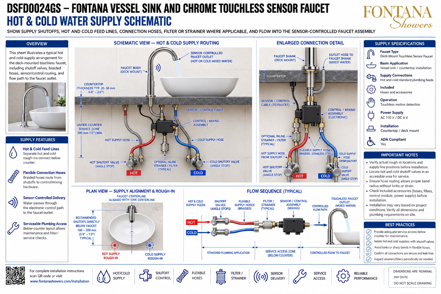
Hot & Cold Water Supply Schematic
This hot- and cold-water supply resource is intended to support plumbing
engineers, contractors, installers, countertop fabricators and maintenance
personnel coordinating the Fontana DSFD0024GS vessel sink and chrome
touchless sensor faucet combination. The drawing package communicates
supply shutoffs, hot and cold feed lines, flexible braided hoses, optional
inline strainer / filter, sensor-control wiring, electronic control /
mixing assembly, faucet connection and the required below-counter service
zone for a clean and maintainable installation.
Fontana DSFD0024GS Touchless Faucet Water-Supply System
The DSFD0024GS uses separate hot and cold plumbing feeds beneath
the countertop. Each supply is controlled by an accessible shutoff
valve and routed through flexible braided hoses toward the
sensor-controlled electronic control / mixing assembly. An optional
inline strainer may be included where applicable before the
controlled water path continues to the faucet outlet.
-
Model:
DSFD0024GS
-
Faucet type:
Deck-mounted touchless sensor faucet
-
Basin application:
Vessel sink / countertop installation
-
Water supplies:
Separate hot and cold feeds
-
Supply connections:
Standard plumbing feeds with flexible braided hoses
-
Operation:
Touchless motion detection
-
Control arrangement:
Electronic control / mixing assembly
-
Optional protection:
Inline strainer / filter where applicable
-
Power supply:
AC 110 V / DC 6 V
-
Installation:
Countertop / deck mount
-
Typical countertop thickness:
Approx. 20–50 mm (0.8–2.0 in.)
-
Recommended under-counter service zone:
Approx. 300 mm (12 in.) minimum
-
Typical shutoff location:
Approx. 100–200 mm (3.9–7.9 in.) below faucet area
Required Hot & Cold Water Supply Drawing Package
Each plumbing coordination drawing should use a consistent faucet
centerline, countertop datum and hot / cold supply identification.
The package should clearly identify shutoff valves, flexible hoses,
optional strainer / filter, electronic control / mixing assembly,
sensor / control cable, faucet connection, supply rough-ins and
below-counter service access before final installation.
Hot & Cold Water Supply Schematic
Provides the complete supply relationship from the hot and
cold rough-ins through shutoff valves, flexible hoses,
optional filtration, the electronic control assembly and
the sensor-controlled faucet outlet.
Schematic View — Hot & Cold Supply Routing
Shows the hot-water supply on the left and cold-water supply
on the right, each routed through accessible angle stops and
flexible hoses toward the under-counter control assembly.
Hot & Cold Feed Lines
Identifies separate hot and cold plumbing rough-ins below
the countertop for organized supply routing and independent
service isolation.
Accessible Shutoff Valves
Shows dedicated hot and cold angle-stop shutoff valves that
remain accessible for faucet maintenance, hose replacement,
filter service and leak inspection.
Flexible Braided Supply Hoses
Coordinates flexible hoses between the shutoff valves and
control assembly, maintaining smooth bend radii without
kinks, twisting or excessive tension.
Optional Inline Strainer / Filter
Identifies a typical inline strainer where applicable to
help prevent construction debris or sediment from entering
the electronic control and mixing components.
Electronic Control / Mixing Assembly
Shows the below-counter control assembly receiving hot and
cold supply feeds and controlling water delivery to the
touchless faucet in response to the sensor signal.
Plan View — Supply Alignment & Rough-In
Shows the faucet centerline aligned with the sink centerline
and typical hot / cold rough-in locations positioned below
and to either side of the faucet.
Typical Flow Sequence
Summarizes the supply path as hot / cold feeds → shutoff
valves → flexible hoses → optional filter / strainer →
sensor / control assembly → controlled faucet outlet.
Engineering note:
All supply-routing dimensions and component positions shown are
nominal coordination references. Final shutoff locations, hose
lengths, filter arrangement, control / mixing assembly configuration,
countertop thickness, power arrangement, supply pressure and service
clearances should be verified against the actual Fontana DSFD0024GS
components and approved installation documentation before rough-in
or final installation.
Plumbing, Control and Service Coordination Considerations
Supply Orientation
Keep hot water on the left and cold water on the right where
practical so installers and maintenance personnel can quickly
identify each supply.
Shutoff Accessibility
Locate both angle stops where they can be reached without
removing permanent cabinetry, the vessel sink or unrelated
plumbing components.
Hose Routing
Maintain smooth hose curves and sufficient service slack
while preventing sharp bends, twisting, tension or contact
with rough cabinet edges.
Filter / Strainer Access
Where an inline strainer is provided, keep it accessible
for periodic cleaning, flushing, inspection and replacement.
Controller & Sensor Cable
Keep the electronic control assembly and sensor cable dry,
protected from sharp hardware and positioned where electrical
connections remain accessible.
Under-Counter Service Zone
Maintain approximately 300 mm (12 in.) of practical service
space beneath the countertop for valves, hoses, filter,
controller and faucet connections.
Water-Supply Installation Best Practices
Flush Supply Lines
Flush hot and cold plumbing feeds before connecting the
faucet system to help remove construction debris and
sediment.
Confirm Rough-In Locations
Verify the actual supply and shutoff positions against the
basin footprint, drain location and under-counter service
zone before final plumbing installation.
Check Hose Connections
Confirm all flexible hose connections are properly seated,
tightened and free from leaks after the water supplies are
pressurized.
Protect Control Wiring
Route the sensor / control cable away from sharp edges,
drain components, pinch points and potential standing water.
Maintain Service Access
Do not conceal the control assembly, shutoff valves,
strainer or hose connections behind permanent inaccessible
panels.
Final Functional Test
After installation, verify sensor activation, controlled
water flow, automatic shutoff and leak-free hot and cold
supply connections.
FontanaShowers Installation and Specification Resources
Professional Engineering and Accessibility References
Project verification:
Hot and cold water-supply schematics are coordination tools and do not
replace approved project submittals. The architect, plumbing engineer,
contractor and licensed installer should verify hot / cold supply
locations, shutoff-valve access, hose lengths, filter arrangement,
control / mixing assembly configuration, power requirements, countertop
thickness, operating pressure, service access and locally adopted
plumbing requirements before rough-in and final installation.
|
|
|