Fontana Touchless Faucet & Vessel Sink Systems™ |
Architectural and Engineering Resource
Fontana DSFD0024GS Vessel Sink and Chrome Touchless Sensor Faucet:
Service & Maintenance Access Drawing
This service and maintenance coordination resource is intended to support
architects, plumbing engineers, contractors, installers, facility managers
and service technicians coordinating the Fontana DSFD0024GS vessel sink
and chrome touchless sensor faucet system. The drawing package identifies
the recommended under-counter service zone, faucet-removal clearance,
flexible hose routing, sensor-cable access, controller placement,
water-resistant solenoid enclosure, power-module access, drain servicing
and minimum cabinet clearances required for reliable long-term maintenance.

Fontana DSFD0024GS Serviceable Under-Counter Assembly
The DSFD0024GS is designed with its primary serviceable components
located beneath the countertop. The faucet mounting hardware,
hot and cold shutoff valves, flexible supply hoses, sensor cable,
electronic controller, water-resistant solenoid enclosure,
power module, drain tailpiece and P-trap should remain accessible
after final cabinet installation so maintenance can be completed
without disturbing the vessel sink or countertop.
-
Model:
DSFD0024GS
-
Faucet type:
Chrome deck-mounted touchless sensor faucet
-
Basin type:
Ceramic vessel sink
-
Supply connections:
1/2-inch hot and cold
-
Control type:
Electronic control module
-
Valve type:
Water-resistant solenoid enclosure
-
Power options:
AC adapter or DC 6 V battery pack
-
Drain configuration:
Pop-up or grid drain with tailpiece and P-trap
-
Minimum vertical faucet-removal clearance:
300 mm (11.8 in.)
-
Minimum rear clearance:
100 mm (3.9 in.)
-
Minimum cabinet service space:
Approx. 300 mm H × 400 mm W × 300 mm D
(11.8 × 15.7 × 11.8 in.)
-
Faucet mounting hole:
Approx. Ø32–35 mm (1.26–1.38 in.), verify actual
Required Service & Maintenance Access Drawing Package
Each service-coordination drawing should clearly identify the
under-counter equipment arrangement, cabinet service envelope,
faucet-removal clearance, mounting-hole location, hot and cold
shutoff valves, flexible hose routing, sensor-cable connection,
controller, solenoid valve, power source and drain components.
All serviceable parts should remain reachable after cabinet and
countertop installation.
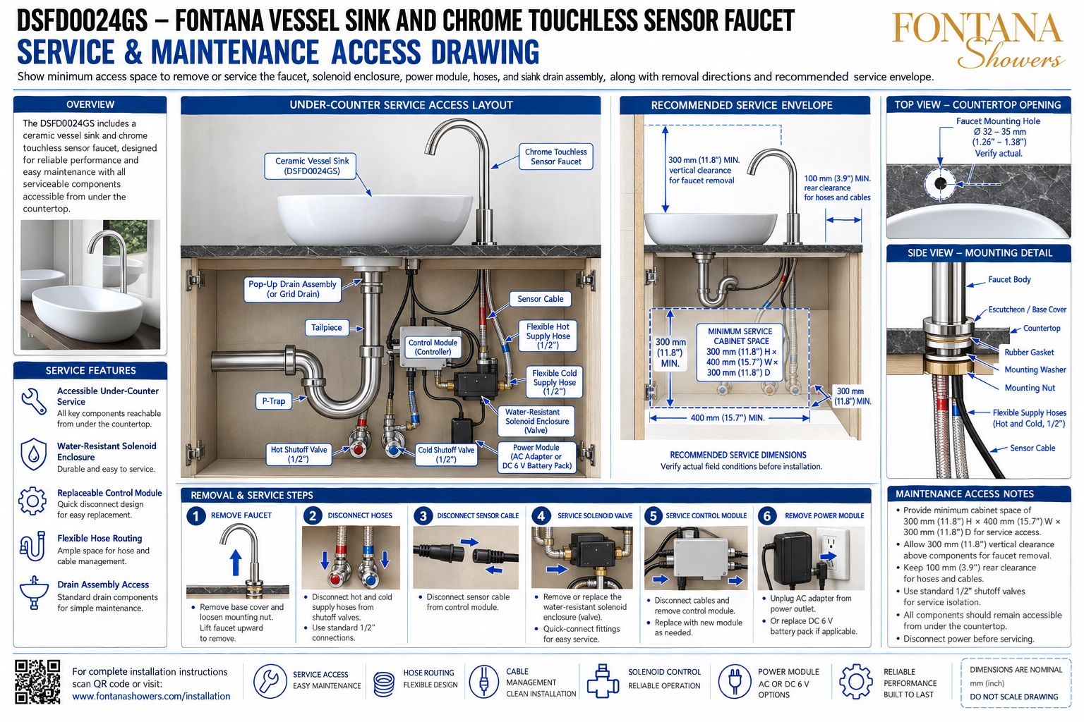
Service & Maintenance Access Drawing
Provides the complete service relationship between the
faucet, vessel sink, supply system, controls, solenoid,
power module, drain assembly and surrounding cabinet space.
Under-Counter Service Access Layout
Shows all major plumbing and electronic components organized
beneath the countertop so they can be reached from the cabinet
interior for inspection and replacement.
Recommended Service Envelope
Identifies a minimum cabinet service zone of approximately
300 mm high × 400 mm wide × 300 mm deep
(11.8 × 15.7 × 11.8 in.).
Faucet Removal Clearance
Shows approximately 300 mm (11.8 in.) minimum vertical
clearance to provide room for loosening mounting hardware
and removing the faucet.
Rear Hose & Cable Clearance
Maintains approximately 100 mm (3.9 in.) minimum rear
clearance for flexible supply hoses, sensor cable and
power wiring.
Top View — Countertop Opening
Identifies a typical faucet mounting hole of approximately
Ø32–35 mm (1.26–1.38 in.). The actual requirement should
be verified before drilling.
Side View — Faucet Mounting Detail
Shows the faucet body, escutcheon, countertop, rubber gasket,
mounting washer, mounting nut, supply hoses and sensor cable
at the deck penetration.
Removal & Service Sequence
Summarizes the typical maintenance sequence for faucet
removal, hose disconnection, sensor-cable disconnection,
solenoid service, controller replacement and power-module
removal.
Drain & Trap Service Access
Maintains access to the pop-up or grid drain, tailpiece,
P-trap and building-drain connection for cleaning,
adjustment and leak inspection.
Engineering note:
All service clearances, mounting-hole dimensions and component
positions shown are nominal coordination references. Final cabinet
size, faucet-removal clearance, rear hose space, mounting-hole
diameter, drain configuration, hose routing, controller position,
solenoid access, power-module location and maintenance requirements
should be verified against the actual Fontana DSFD0024GS components
and approved installation documentation before final construction.
Under-Counter Service Access Components
Hot Shutoff Valve
The hot-water shutoff should remain clearly visible and
reachable so the supply can be isolated before hose,
solenoid or faucet maintenance.
Cold Shutoff Valve
The cold-water shutoff should remain accessible independently
of the hot supply for safe service and troubleshooting.
Flexible Supply Hoses
Provide enough room around both 1/2-inch supply hoses for
disconnection, inspection and replacement without sharp
bends or excessive tension.
Sensor Cable
The sensor cable should remain accessible for quick
disconnection from the controller and should be protected
from abrasion, moisture and crushing.
Control Module
Mount the electronic controller where cables can be
disconnected and the module can be removed without
disturbing surrounding plumbing.
Solenoid Enclosure
Keep the water-resistant solenoid assembly accessible so
water connections and control leads can be serviced
independently.
Recommended Service Envelope & Cabinet Clearances
300 mm Minimum Service Height
Maintain approximately 300 mm (11.8 in.) of clear vertical
space around the primary under-counter components.
400 mm Minimum Service Width
Provide approximately 400 mm (15.7 in.) of clear cabinet
width so technicians can reach the controller, solenoid
and shutoff valves.
300 mm Minimum Service Depth
Maintain approximately 300 mm (11.8 in.) of usable depth
for hand and tool access during servicing.
Faucet Removal Zone
Keep the vertical area beneath and around the faucet
mounting hardware open enough to loosen the retaining
hardware and lift the faucet for removal.
Rear Service Clearance
Preserve at least the illustrated 100 mm (3.9 in.) rear
space for hose bends, cable routing and connector access.
Maintenance Reach Area
Keep fixed shelving, drawers and unrelated equipment outside
the main maintenance reach zone wherever practical.
Faucet Mounting & Removal Coordination
Mounting Hole
The drawing identifies an approximate Ø32–35 mm
(1.26–1.38 in.) faucet penetration. Verify the actual
component before countertop drilling.
Escutcheon / Base Cover
The chrome base cover should be removable so the faucet
mounting hardware can be accessed during service.
Rubber Gasket
Inspect the sealing gasket during faucet removal and replace
it if damaged, compressed unevenly or deteriorated.
Mounting Washer
Keep the washer accessible beneath the countertop so the
faucet can be loosened or retightened without removing
unrelated components.
Mounting Nut
The retaining nut should remain reachable with standard
service tools and should not be blocked by plumbing or
cabinet framing.
Vertical Removal Path
After the retaining hardware and service connections are
disconnected, the faucet should be able to lift upward
without obstruction.
Typical Removal & Service Sequence
1. Remove Faucet
Remove the faucet base cover, loosen the mounting hardware
from below the countertop and lift the faucet vertically
for removal.
2. Disconnect Supply Hoses
Close both shutoff valves, then disconnect the hot and cold
supply hoses using the appropriate service tools.
3. Disconnect Sensor Cable
Disconnect the sensor cable from the controller by handling
the connector rather than pulling on the wire itself.
4. Service Solenoid Valve
Isolate the water and power, disconnect the quick-connect
fittings and remove or replace the water-resistant solenoid
enclosure as required.
5. Service Control Module
Disconnect the controller cables, remove the module from
its mounting position and install a replacement unit if needed.
6. Remove Power Module
For AC installations, unplug the adapter. For DC operation,
remove or replace the 6 V battery pack as applicable.
Drain, Trap & Plumbing Service Coordination
Drain Assembly
Keep the pop-up or grid drain assembly accessible for
resealing, adjustment and replacement.
Tailpiece
The vertical tailpiece should remain visible and removable
without interference from electrical controls or cabinet
framing.
P-Trap
Maintain direct access to the P-trap for cleaning,
unclogging, leak inspection and replacement.
Building Drain Connection
Keep the trap-arm connection accessible enough to inspect
and adjust the waste connection where required.
Plumbing Isolation
Use accessible hot and cold shutoff valves so faucet and
solenoid service can be completed without shutting down
unrelated fixtures.
Leak Inspection
Keep supply and drain connections visible enough for routine
inspection during commissioning and future maintenance.
Hose Routing & Cable Management
Hose Bend Radius
Route flexible hoses with smooth curves and sufficient
bend radius to prevent kinking and stress at fittings.
Service Slack
Provide enough hose and cable slack to permit component
removal without placing tension on connections.
Cable Separation
Keep sensor and power cables separated from sharp fittings,
heat sources and potential leak points wherever practical.
Connector Visibility
Keep electrical connectors visible and reachable so they
can be disconnected quickly during maintenance.
Avoid Pinching
Do not route hoses or cables where cabinet doors, drawers,
fasteners or removable panels can pinch or crush them.
Dry Routing Zone
Keep controller and power cables away from standing water
and directly below leak-prone fittings whenever practical.
Service & Maintenance Best Practices
Isolate Water Before Service
Close both hot and cold shutoff valves before disconnecting
hoses, the solenoid valve or faucet components.
Disconnect Power
Unplug the AC adapter or disconnect the DC battery source
before servicing the controller or solenoid assembly.
Maintain Cabinet Clearance
Do not use the recommended maintenance envelope for
permanent storage or fixed accessories.
Inspect Hose Condition
Check flexible hoses periodically for abrasion, corrosion,
kinking or signs of leakage.
Check Electrical Components
Inspect controller connections, sensor wiring and the power
module for secure connections and moisture exposure.
Test After Service
After reassembly, restore water and power and verify
touchless activation, automatic shutoff and leak-free operation.
Final Serviceability Verification
Faucet Access
Confirm the faucet mounting nut and washer can be reached
from below and the faucet has a clear removal path.
Supply Access
Verify both shutoff valves and flexible hoses can be
inspected and disconnected without removing cabinet parts.
Control Access
Confirm the controller and solenoid valve remain visible,
reachable and removable.
Power Access
Ensure the AC adapter or DC battery pack can be serviced
without disturbing plumbing components.
Drain Access
Verify the drain assembly, tailpiece and P-trap remain
accessible for cleaning and leak inspection.
Clear Service Envelope
Confirm the final cabinet arrangement preserves the
recommended service area and does not obstruct future
maintenance.
FontanaShowers Installation and Service Resources
Professional Plumbing, Electrical & Service References
Project verification:
Service and maintenance drawings are coordination tools and do not
replace approved project submittals or manufacturer instructions.
The architect, plumbing engineer, electrical engineer, contractor,
cabinet fabricator and licensed installer should verify cabinet
dimensions, faucet-removal clearance, mounting-hole size, shutoff-valve
access, supply-hose routing, sensor-cable access, controller placement,
solenoid configuration, power-source location, drain access and locally
applicable plumbing and electrical requirements before final installation.
|
|
|