Fontana Touchless Faucet Systems™ |
Architectural and Engineering Resource
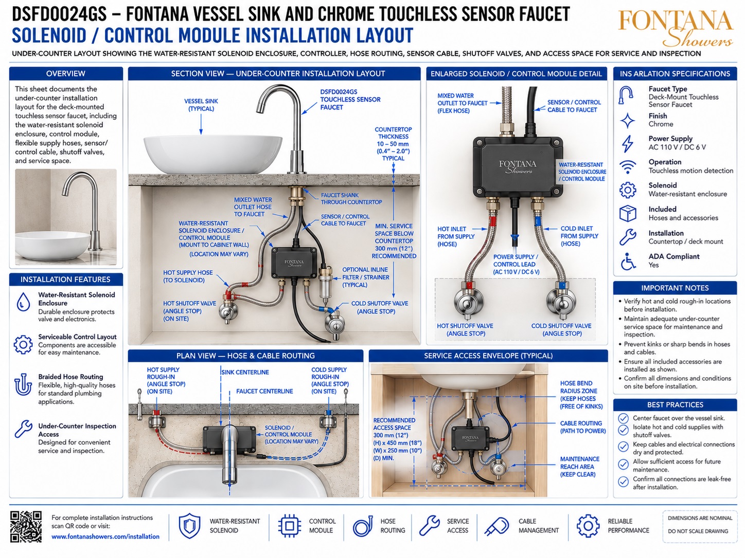
Fontana DSFD0024GS Vessel Sink and Chrome Touchless Sensor Faucet:
Solenoid / Control Module Installation Layout
This under-counter installation resource is intended to support plumbing
engineers, contractors, installers, millwork fabricators and maintenance
personnel coordinating the Fontana DSFD0024GS vessel sink and chrome
touchless sensor faucet combination. The drawing package communicates
the water-resistant solenoid enclosure, electronic control module,
flexible hose routing, sensor / control cable, hot and cold shutoff
valves, optional inline filtration, power connection and recommended
service-access envelope required for reliable touchless faucet operation.
Fontana DSFD0024GS Under-Counter Control & Solenoid Assembly
The DSFD0024GS touchless faucet uses an under-counter electronic
control and solenoid assembly to regulate water delivery in
response to the faucet sensor. Separate hot and cold supplies
connect through accessible shutoff valves and flexible braided
hoses, while the mixed-water outlet continues from the controller
to the faucet shank above the countertop.
-
Model:
DSFD0024GS
-
Faucet type:
Deck-mount touchless sensor faucet
-
Finish:
Chrome
-
Operation:
Touchless motion detection
-
Power supply:
AC 110 V / DC 6 V
-
Solenoid assembly:
Water-resistant enclosure
-
Installation:
Countertop / deck mount
-
Basin application:
Vessel sink
-
Typical countertop thickness:
Approx. 10–50 mm (0.4–2.0 in.)
-
Recommended service space:
Approx. 300 mm (12 in.) below countertop
-
Typical access envelope:
Approx. 300 × 450 × 250 mm
(12 × 18 × 10 in.)
-
Included system elements:
Hoses, control components, sensor / control wiring
and related accessories
Required Solenoid / Control Module Installation Drawing Package
Each under-counter coordination drawing should use a consistent
countertop datum, faucet centerline and hot / cold supply
identification. The package should clearly identify the
water-resistant solenoid enclosure, control module, flexible supply
hoses, mixed-water outlet, sensor / control cable, power lead,
shutoff valves, optional inline strainer and required maintenance
access before final installation.
Solenoid / Control Module Installation Layout
Provides the complete under-counter relationship between
the faucet shank, hot and cold supplies, shutoff valves,
flexible hoses, control enclosure, wiring and mixed-water
outlet connection.
Section View — Under-Counter Installation
Shows the vessel sink and faucet above the countertop with
the control module, supply hoses, sensor cable and shutoff
valves arranged within the serviceable cabinet area below.
Water-Resistant Solenoid Enclosure
Identifies the enclosed electronic solenoid / control module
that receives hot and cold water, sensor input and power
before sending controlled mixed water to the faucet.
Hot & Cold Supply Connections
Shows separate hot and cold water connections routed through
accessible shutoff valves and flexible braided hoses to the
control assembly.
Mixed-Water Outlet to Faucet
Shows the controlled mixed-water hose leaving the solenoid
assembly and connecting to the faucet shank beneath the
countertop.
Sensor / Control Cable
Identifies the cable connecting the faucet sensor to the
under-counter controller and emphasizes protected routing
free from sharp bends, pinching and moisture exposure.
Plan View — Hose & Cable Routing
Shows the relationship between faucet centerline, sink
centerline, hot / cold rough-ins, control-module location
and routing paths for hoses and electrical connections.
Service Access Envelope
Maintains a practical service zone around the solenoid,
shutoff valves, hoses and cables so components can be
inspected, disconnected and maintained after installation.
Optional Inline Filter / Strainer
Shows an optional serviceable filter or strainer within the
supply path to help protect the solenoid and control
components from debris where applicable.
Engineering note:
The under-counter component locations and clearances shown are
nominal coordination references. Final solenoid position,
controller configuration, hose lengths, shutoff locations, filter
arrangement, cable routing, power connection, countertop thickness
and service envelope should be verified against the actual Fontana
DSFD0024GS components and approved installation documentation
before final installation.
Under-Counter Plumbing, Control and Service Considerations
Solenoid Module Position
Mount the water-resistant control enclosure in a visible,
accessible location where water and electrical connections
can be inspected without removing the vessel sink or countertop.
Shutoff Accessibility
Keep both hot and cold angle-stop valves accessible so the
faucet can be isolated quickly for maintenance, inspection
or hose replacement.
Hose Bend Radius
Route flexible braided hoses using smooth curves and adequate
slack while avoiding kinks, twisting, sharp bends and excessive
tension on fittings.
Cable Management
Route sensor and power wiring separately from sharp plumbing
hardware, protect cables from pinch points and maintain enough
slack for future service.
Moisture Protection
Even with a water-resistant enclosure, position the controller
away from direct leaks, standing water and areas subject to
frequent condensation.
Maintenance Reach Zone
Keep the controller, shutoff valves, filter and hose
connections within an unobstructed reach area for routine
inspection and future component replacement.
Solenoid & Control Module Installation Best Practices
Verify Rough-In Locations
Confirm hot and cold water rough-ins, faucet position,
countertop thickness and cabinet clearances before mounting
the control assembly.
Secure the Enclosure
Mount the solenoid / control enclosure securely to a suitable
cabinet or wall surface while keeping all connection points
accessible.
Protect Flexible Hoses
Keep supply and outlet hoses away from sharp cabinet hardware,
moving drawers and areas where they may become pinched or
abraded.
Protect Electrical Connections
Keep sensor cables, power leads and connectors dry, supported
and clear of plumbing joints where leaks could occur.
Maintain Service Space
Preserve approximately 300 mm (12 in.) of recommended
below-counter service height and maintain practical width
and depth around the control assembly.
Leak & Function Testing
After installation, pressurize the system, inspect every
hose connection for leaks and verify touchless activation,
controlled flow and automatic shutoff.
Final Installation & Commissioning Verification
Water-Supply Check
Confirm the hot and cold supplies are connected to the
correct control-module inlets and both shutoff valves
operate freely.
Mixed-Water Outlet Check
Verify the controlled outlet hose is securely connected
between the solenoid assembly and faucet shank without
kinks or excessive tension.
Sensor Connection Check
Confirm the sensor / control cable is fully seated, protected
and routed so it cannot be accidentally disconnected during
normal cabinet use.
Power Check
Verify the specified AC or DC power source is connected
correctly and remains accessible for future maintenance.
Touchless Operation
Test sensor activation and confirm that the solenoid opens
and closes reliably during normal hand entry and removal.
Service Access Check
Confirm the final cabinet installation leaves sufficient
clearance around the controller, valves, hoses, filter and
electrical connections for maintenance.
FontanaShowers Installation and Specification Resources
Professional Engineering and Accessibility References
Project verification:
Solenoid and control-module installation drawings are coordination
tools and do not replace approved project submittals. The architect,
plumbing engineer, contractor and licensed installer should verify
solenoid location, controller configuration, hot and cold supply
orientation, shutoff-valve access, hose routing, filter arrangement,
sensor wiring, power requirements, cabinet clearances, maintenance
access and locally adopted plumbing or electrical requirements before
final installation and commissioning.
|
|
|