Fontana Touchless Fixtures™ | Architectural and Engineering Resource
Fontana Combination Faucet & Soap Dispenser:
Cabinet Clearance & Maintenance Drawing
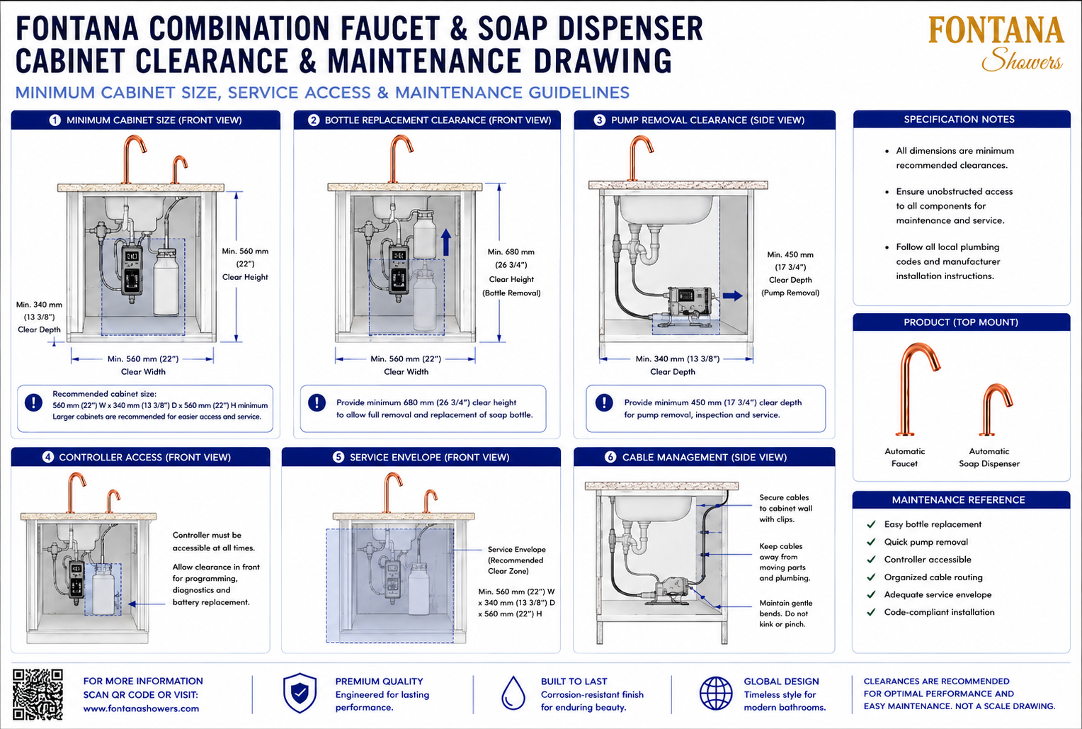
This cabinet-clearance and maintenance resource is intended to support
architects, plumbing engineers, cabinet manufacturers, contractors,
installers and facility managers coordinating a Fontana countertop touchless
faucet and automatic soap dispenser within commercial and residential lavatory
environments. The drawing identifies the recommended cabinet envelope,
bottle-removal clearance, pump-service depth, controller access,
cable-management requirements and under-counter service zone.
Fontana Touchless Faucet and Automatic Soap Dispenser Cabinet Layout
This coordinated under-counter installation arranges the controller,
soap reservoir, pump, plumbing connections and electrical components
within a serviceable cabinet space. The illustrated clearances support
routine inspection, bottle replacement, pump removal, programming,
battery access and organized cable routing.
- Fixture configuration: Countertop touchless faucet and automatic soap dispenser
- Installation: Deck mounted / countertop mounted
- Minimum cabinet width: 560 mm (22 in.)
- Minimum cabinet depth: 340 mm (13-3/8 in.)
- Minimum cabinet height: 560 mm (22 in.)
- Bottle-removal clearance: 680 mm (26-3/4 in.) minimum clear height
- Pump-removal clearance: 450 mm (17-3/4 in.) minimum clear depth
- Controller access: Unobstructed for programming and diagnostics
- Service envelope: Maintain clear access around all components
- Cable routing: Secure to cabinet surfaces with clips
- Tubing and wiring: Keep clear of moving parts and sharp edges
- Application: Commercial and residential lavatories
Required Cabinet Clearance and Maintenance Drawing Package
Each drawing should use a consistent cabinet reference, component
identification system and service-clearance notation. The package should
clearly identify the minimum cabinet dimensions, soap-bottle removal path,
pump-service depth, controller access zone, cable routing and complete
maintenance envelope. Components should remain accessible without requiring
removal of unrelated plumbing or electrical equipment.
Cabinet Clearance Overview
Shows the complete under-counter service arrangement for the faucet and soap-dispenser system. This drawing provides an overall reference for cabinet design, component placement and maintenance planning.
Minimum Cabinet Size
Defines a recommended minimum interior envelope of 560 mm wide, 340 mm deep and 560 mm high. Larger dimensions are encouraged where additional service space is available.
Bottle Replacement Clearance
Illustrates the upward removal path for the soap reservoir and identifies a minimum clear height of 680 mm. The bottle should be removable without disconnecting adjacent components.
Pump Removal Clearance
Shows the side-service space required to inspect, remove and replace the pump assembly. A minimum unobstructed depth of 450 mm is recommended.
Controller Access
Identifies the clear area required in front of the electronic controller for programming, diagnostics, connector inspection and battery replacement.
Service Envelope
Coordinates the complete recommended clear zone surrounding the controller, reservoir, pump, plumbing and electrical components for ongoing inspection and maintenance.
Cable Management
Shows cables secured to cabinet surfaces with suitable clips and routed away from moving parts, sharp edges, moisture and plumbing connections.
Tubing and Hose Routing
Coordinates soap tubing and water-supply hoses so they remain free from kinks, compression, abrasion and interference with removable components.
Maintenance Access
Confirms that the bottle, pump, controller, connectors and power components can be serviced without removing the faucet or soap dispenser from the countertop.
Engineering note:
The cabinet-clearance drawing is a coordination reference and should not
be scaled. Verify cabinet dimensions, component positions, service paths,
plumbing connections, electrical access and cable routing against the
current product specification, approved shop drawings and installation
instructions before cabinet fabrication or fixture installation.
Installation and Maintenance Coordination Considerations
Cabinet Envelope
Maintain at least the recommended interior width, depth and height while allowing additional space where plumbing or cabinetry conditions require it.
Bottle Access
Keep the vertical removal path clear so the soap bottle can be lifted out, refilled and reinstalled without disturbing adjacent components.
Pump Servicing
Provide sufficient side clearance for pump inspection, disconnection, removal and replacement.
Controller Visibility
Mount the controller where labels, connectors and service controls remain visible and reachable during commissioning and maintenance.
Cable Protection
Use approved clips and gentle bends to prevent cable strain, abrasion and contact with sharp cabinet edges.
Moisture Separation
Keep electrical components away from likely leak paths and provide access for inspection of water and soap connections.
FontanaShowers Installation and Specification Resources
FontanaShowers Product Catalog
Product information, finish options and technical documentation for Fontana touchless bathroom and commercial fixtures.
FontanaShowers Installation Hub
Central installation resource for touchless faucets, automatic soap dispensers and associated under-counter components.
Automatic Sensor Faucet Collection
Explore touchless faucet systems, power options, controllers and commercial handwashing applications.
Faucet BIM and Design Resources
Architectural and coordination resources supporting fixture selection, project documentation and model development.
Soap Dispenser Resources
Product and installation information for soap bottles, pumps, tubing, controllers and maintenance requirements.
Fixture Installation Resources
General installation information covering component mounting, cable routing, testing, cleaning and maintenance.
Professional Engineering and Accessibility References
Project verification:
Cabinet-clearance and maintenance drawings are coordination tools and do not
replace approved project submittals. The architect, plumbing engineer,
cabinet fabricator, contractor and qualified installer should verify cabinet
dimensions, service clearances, component locations, bottle and pump removal
paths, controller access, cable routing, moisture protection and applicable
local codes before fabrication and installation.
|
|
|