Fontana Touchless Fixtures™ | Architectural and Engineering Resource
Fontana Countertop Faucet & Soap Dispenser:
Under-Counter Component Layout
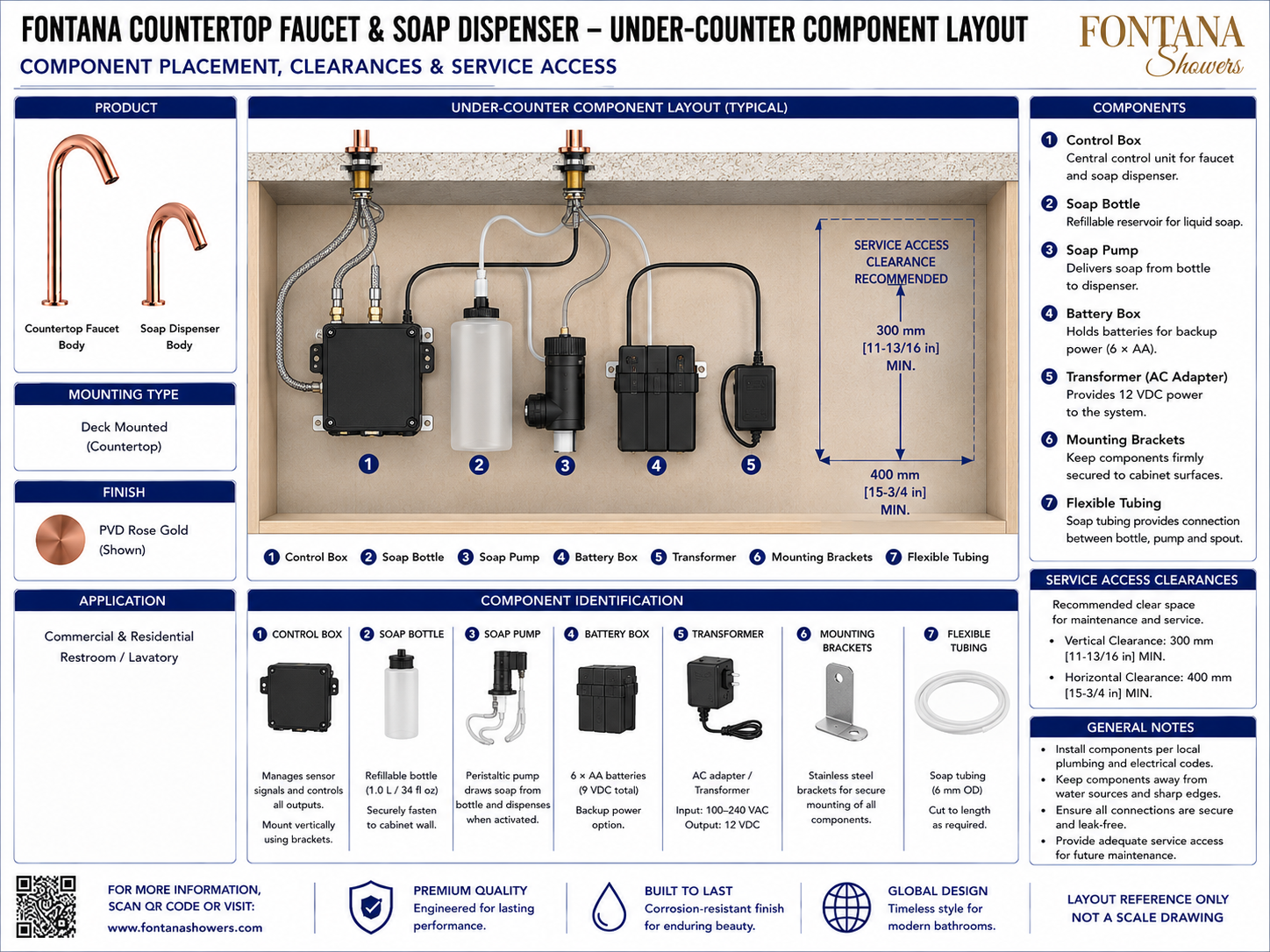
This under-counter component layout resource is intended to support architects,
plumbing engineers, electrical designers, interior designers, contractors,
installers and facility managers coordinating the Fontana countertop touchless
faucet and automatic soap dispenser within commercial and residential lavatory
environments. The drawing identifies the control box, refillable soap bottle,
soap pump, battery box, transformer, mounting brackets, flexible tubing and
recommended service-access clearances beneath the countertop.
Fontana Touchless Faucet and Automatic Soap Dispenser System
This coordinated touchless system organizes the electronic controller,
soap-delivery components and power equipment beneath the countertop.
The illustrated arrangement supports orderly installation, moisture
separation, cable and tubing management, routine refilling, battery
replacement and long-term maintenance access.
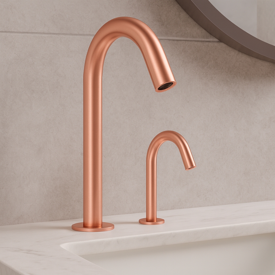
- Fixture set: Countertop touchless faucet and automatic soap dispenser
- Installation: Deck mounted / countertop mounted
- Finish: Rose gold PVD
- Application: Commercial and residential restroom / lavatory
- Control module: Electronic control box
- Soap reservoir: Refillable 1.0 L (34 fl oz) bottle
- Soap pump: Peristaltic automatic dispensing pump
- Backup power: 6 × AA batteries, 9 VDC total
- Primary power: 12 VDC AC adapter / transformer
- Soap tubing: 6 mm OD flexible tubing
- Vertical service clearance: 300 mm (11-13/16 in.) minimum
- Horizontal service clearance: 400 mm (15-3/4 in.) minimum
Required Under-Counter Component Layout Package
Each drawing should use a consistent component numbering system, mounting
reference and service-clearance notation. The package should clearly identify
the control box, soap bottle, pump, battery box, transformer, brackets,
flexible tubing, wiring paths and maintenance zone. Components should be
arranged to remain accessible while avoiding interference with plumbing,
drainage, cabinetry and moving hardware.
Under-Counter Layout Overview
Shows the complete arrangement of the faucet and soap-dispenser components beneath the countertop. This view provides an overall reference for cabinet planning, mounting coordination, utility routing and project submittals.
Control Box
Identifies the central control unit that manages sensor inputs and operates the faucet and soap-dispenser outputs. The control box should be mounted securely and positioned for easy access to ports and wiring.
Soap Reservoir
Shows the refillable 1.0 L soap bottle mounted near the dispenser pump. The bottle should remain upright, securely supported and accessible for refilling, removal and cleaning.
Peristaltic Soap Pump
Illustrates the pump that draws liquid soap from the reservoir and delivers it to the dispenser spout. Tubing connections should remain visible and free from kinks, compression and sharp bends.
Battery Box
Identifies the backup-power enclosure for six AA batteries. The battery box should be mounted where the cover can be opened without removing adjacent plumbing or soap-system components.
Transformer / AC Adapter
Shows the primary 12 VDC power source for the system. The adapter should be positioned in a dry, ventilated and accessible location away from potential water leaks and standing moisture.
Mounting Brackets
Identifies the stainless-steel brackets used to secure components to cabinet surfaces. Fasteners should suit the substrate and prevent movement during operation, refilling and maintenance.
Flexible Tubing
Shows the 6 mm OD soap tubing connecting the bottle, pump and dispenser. Tubing should be cut to the required length and routed without sagging, abrasion, pinching or contact with sharp edges.
Service-Access Zone
Defines a recommended clear maintenance area of at least 300 mm vertically and 400 mm horizontally. Preserve this zone for component removal, inspection, refilling and future replacement.
Engineering note:
The illustrated layout is a coordination reference and should not be scaled.
Verify cabinet dimensions, component mounting locations, electrical access,
soap-tubing lengths, plumbing separation and service clearances against the
current FontanaShowers specification sheet, approved product sample and
installation instructions before fabrication or installation.
Installation and Service Coordination Considerations
Component Mounting
Secure all components to stable cabinet surfaces using suitable brackets and fasteners so they do not move during normal operation or maintenance.
Moisture Separation
Keep the control box, battery box and transformer separated from likely leak paths, drain fittings and areas where standing water may collect.
Tubing Routing
Route soap tubing without kinks, sharp bends or compression, and keep it clear of drawer slides, hinges and other moving cabinet hardware.
Cable Management
Support electrical cables with suitable clips or ties while preserving service loops for inspection and future component replacement.
Refill Access
Position the soap bottle so it can be refilled or removed without disconnecting unrelated plumbing or electrical components.
Maintenance Clearance
Maintain the recommended 300 mm vertical and 400 mm horizontal clear area for safe servicing of the complete under-counter system.
FontanaShowers Installation and Specification Resources
FontanaShowers Product Catalog
Product information, finish options and technical documentation for Fontana touchless bathroom and commercial fixtures.
FontanaShowers Installation Hub
Central installation resource for touchless faucets, automatic soap dispensers and associated under-counter components.
Automatic Sensor Faucet Collection
Explore touchless faucet configurations, power options, control systems and commercial handwashing applications.
Faucet BIM and Design Resources
Architectural and coordination resources supporting fixture selection, project documentation and multidisciplinary model development.
Touchless Soap Dispenser Resources
Product and installation information for soap pumps, refillable bottles, tubing and automatic dispensing systems.
Fixture Installation Resources
General installation information covering mounting, electrical connections, tubing, testing, cleaning and maintenance.
Professional Engineering and Accessibility References
Project verification:
Under-counter layout drawings are coordination tools and do not replace approved
project submittals. The architect, plumbing engineer, electrical designer,
contractor and qualified installer should verify component locations, mounting
surfaces, power access, moisture separation, tubing and cable routing, service
clearances, accessibility criteria and applicable local codes before installation.
|
|
|