Fontana Luxury Shower Systems™ | Architectural and Engineering Resource
Fontana Maubeuge FS6029GMG 3-Function Gun Metal Gray LED Shower Faucet: Concealed Mixer Valve Installation Detail
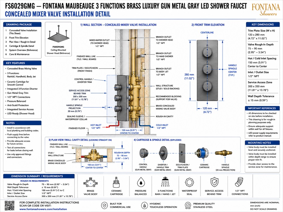
This concealed mixer-valve resource supports architects, plumbing engineers, contractors and installers coordinating the Fontana Maubeuge FS6029GMG three-function shower system. The drawing package communicates the brass mixing valve body, front trim, three-function diverter, ceramic cartridge, hot and cold inlet spacing, branch outlets, rough-in depth, waterproofing interface, structural backing and service-access requirements.
Fontana Maubeuge FS6029GMG Concealed 3-Function Mixer Valve
The FS6029GMG uses a concealed brass mixing valve with integrated three-function diverter, pressure-balanced control and ceramic cartridge. The valve supplies the rainfall shower head, handheld shower and body jet through concealed 1/2 in. NPT branch connections while a Gun Metal Gray trim plate provides the finished control interface.
- Model: FS6029GMG
- Functions: Rainfall, handheld and body jet
- Valve body: Concealed brass mixing valve
- Trim finish: Gun Metal Gray
- Trim plate size: 120 × 280 mm (4.72 × 11.02 in.)
- Valve rough-in depth: 75–90 mm (2.95–3.54 in.)
- Wall-depth tolerance: ±15 mm (0.59 in.)
- Hot / cold inlet spacing: 150 mm (5.91 in.) center to center
- Inlet / outlet size: 1/2 in. NPT
- Service-access zone: 300 × 350 mm (11.81 × 13.78 in.)
- Handle-spindle projection: Approximately 20 mm (0.79 in.)
Required Concealed Mixer Valve Drawing Package
Each installation drawing should use a consistent finished-wall datum, centerline convention and component identification system. The package should clearly identify valve depth, inlet spacing, branch outlets, trim plate location, handle-spindle projection, cartridge assembly, service access, structural support and waterproofing transitions before wall closure.
Concealed Mixer Valve Installation Detail
Shows the complete concealed-valve arrangement, including the brass valve body, trim plate, diverter controls, service-access zone, hot and cold inlets, mixed-water outlet and branch connections to the rain head, hand shower and body jet.
Wall Section — Concealed Valve
Illustrates the valve body secured within the wall structure with the finished-wall line, trim plate, sealing sleeve, backing and rough-in cavity identified for depth and piping coordination.
Front Trim Elevation
Defines the Gun Metal Gray trim plate at approximately 120 × 280 mm with three circular controls aligned vertically along the centerline.
Plan View / Wall Cavity
Shows the concealed valve body between the wall structure and finished surface, with hot and cold supply spacing of approximately 150 mm center to center and a nominal rough-in depth of 75–90 mm.
Hot & Cold Inlets
Identifies the hot-water inlet on the left and cold-water inlet on the right, both using nominal 1/2 in. NPT connections.
Branch Outlet Connections
Coordinates the mixed-water outlet to the shower head and branch outlets to the hand shower and body jet, each identified as nominal 1/2 in. NPT.
Service-Access Zone
Shows a nominal 300 × 350 mm access area behind the trim assembly for future cartridge, diverter, valve, seal and connection maintenance.
Cartridge & Spindle Detail
The exploded assembly identifies the control handle, diverter trim, escutcheon, ceramic cartridge and handle spindle, with an approximate 20 mm spindle projection.
Waterproofing & Structural Support
Coordinates the sealing sleeve or waterproof collar around the valve penetration and the blocking that supports the brass valve body.
Engineering note: All dimensions shown are nominal and intended for rough-in coordination. Final valve depth, supply spacing, outlet routing, service-access dimensions, waterproofing details, cartridge configuration, structural support and finished trim position should be verified against the approved Fontana Maubeuge FS6029GMG installation documentation.
Architectural, Plumbing and Waterproofing Coordination Considerations
Valve Rough-In Depth
Maintain the valve body within the indicated 75–90 mm range from the finished-wall plane and account for tile, setting materials, waterproofing and wall board.
Wall-Depth Tolerance
Coordinate the installation within the shown ±15 mm tolerance so the trim plate and handles seat correctly after final wall finishes are applied.
Supply Spacing
Keep the hot and cold inlets approximately 150 mm center to center and confirm the left-hot / right-cold orientation before pressure testing.
Structural Blocking
Provide rigid backing or framing support for the concealed valve body so handle operation and future servicing do not cause movement.
Waterproof Seal
Integrate the sealing sleeve or waterproof collar with the project waterproofing system and maintain continuity around the valve penetration.
Future Service
Preserve access to the cartridge, diverter and valve connections so service can be completed without unnecessary removal of permanent wall construction.
FontanaShowers Installation and Specification Resources
Professional Engineering and Construction References
Project verification: Concealed mixer-valve drawings are coordination tools and do not replace approved project submittals. The architect, plumbing engineer, waterproofing consultant, contractor and licensed installer should verify valve depth, supply spacing, branch connections, trim alignment, cartridge access, waterproofing transitions, structural support, service-zone dimensions and locally adopted plumbing requirements before wall closure and finish installation.
|
|
|