Fontana Large Rain Shower Systems™ | Architectural and Engineering Resource
Fontana Large Rain Shower Head System: LED Lighting & Electrical Wiring Diagram
This electrical coordination resource is intended to support architects, electrical engineers, plumbing designers, interior designers, contractors, installers and facility managers coordinating the Fontana large rain shower head system with integrated perimeter LED lighting. The drawing package communicates the 600 x 600 mm shower head, ceiling mount arm, LED driver / transformer, RF lighting controller, 12 VDC low-voltage cabling, IP68 waterproof connectors, grounding, service access, ceiling-cavity clearance and recommended electrical installation zones.
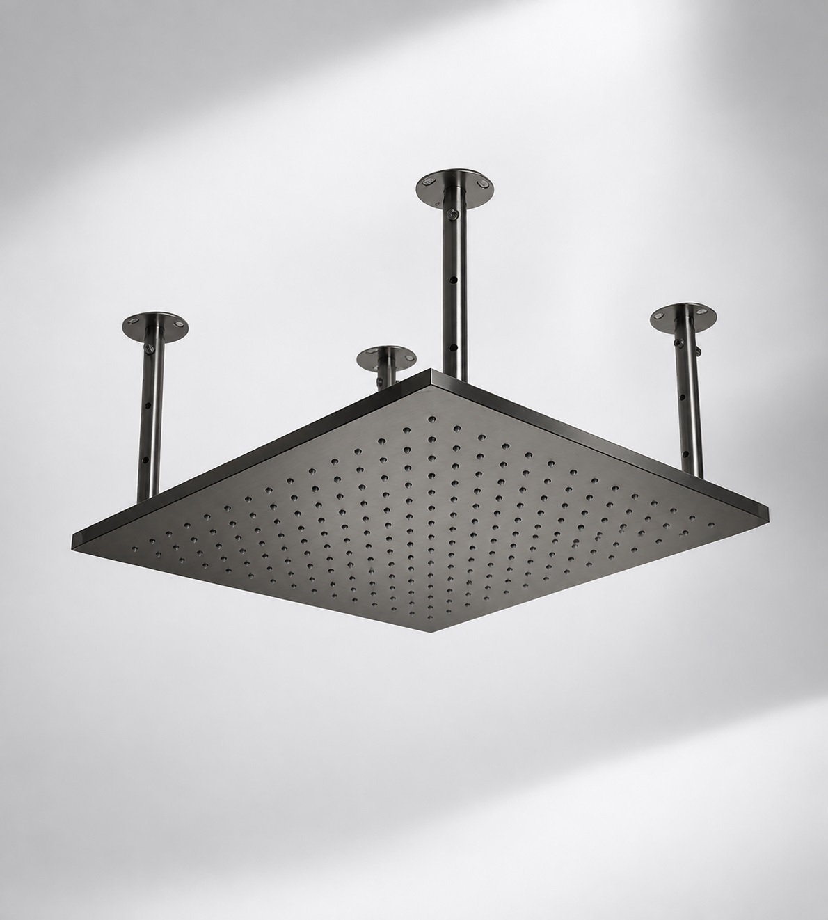
Fontana Large Rain Shower Head with Integrated LED Lighting
The system combines a large ceiling-mounted stainless-steel rain shower head with integrated warm-white perimeter lighting and concealed low-voltage electrical components. A 120 VAC supply feeds the LED driver / transformer, which provides 12 VDC power to the RF controller and shower-head lighting. Electrical equipment is intended to remain dry, accessible and outside the direct spray zone while low-voltage connections use waterproof fittings.
- Shower-head size: 600 x 600 mm (23.62 x 23.62 in.)
- Integrated lighting: Perimeter LED, approximately 3000K
- LED operating voltage: 12 VDC
- LED load: Approximately 48 W
- Driver input: 120 VAC, 60 Hz
- Driver output: 12 VDC, maximum approximately 60 W
- Lighting control: PWM LED controller with 2.4 GHz RF remote
- Low-voltage cable: 12 VDC Class 2; maximum run shown 10 m (32.8 ft)
- Waterproof connectors: IP68
- Ceiling mount arm: 300 mm (11.81 in.) long
- Recommended service access: Minimum 400 x 400 mm (15.75 x 15.75 in.)
Required LED Lighting and Electrical Drawing Package
Each electrical drawing should use a consistent component identification system, voltage notation and installation-zone reference. The package should clearly distinguish mains-voltage wiring from Class 2 low-voltage wiring, identify grounding and bonding conductors, show accessible driver and controller locations, define waterproof connection points and coordinate all electrical components with the finished ceiling and wet-area boundaries.
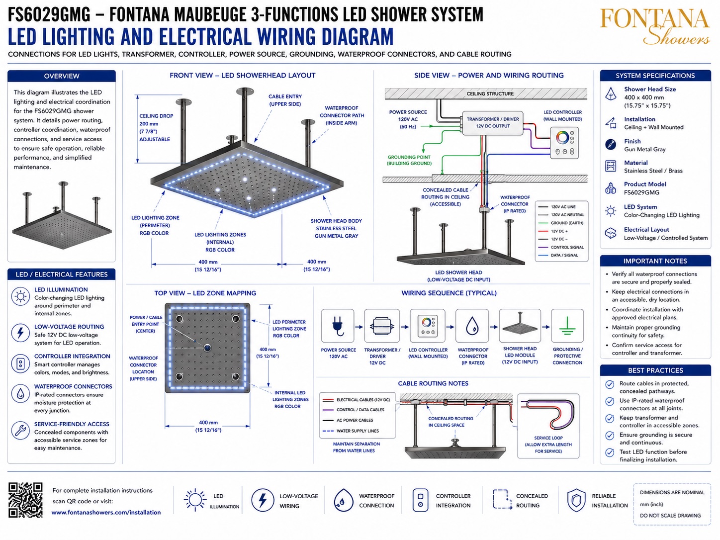
LED Lighting & Electrical Wiring Diagram
Shows the complete relationship between the 600 mm rain shower head, 120 VAC supply, LED driver / transformer, 12 VDC lighting controller, waterproof connectors, low-voltage cable, equipment grounding and ceiling mounting assembly. This is the primary electrical coordination reference for installation and project submittals.
Front / Bottom Elevation
Displays the 600 mm square shower head as viewed from below and identifies the integrated LED perimeter, anti-clog rain nozzles, low-voltage wire exit and 300 mm ceiling mount arm. This view supports ceiling layout and fixture centerline coordination.
Side Section - Installation & Wiring
Illustrates the concealed ceiling cavity, LED driver, RF controller, waterproof connectors, low-voltage cable, grounding path, mounting arm and shower head. The section indicates a minimum 150 mm (5.91 in.) ceiling-cavity depth.
LED Driver / Transformer
Identifies the driver as the interface between the dedicated 120 VAC supply and the 12 VDC lighting circuit. The driver should be mounted on solid structure, remain accessible for service and be kept outside the direct spray area with ventilation clearance.
LED Controller / RF Receiver
Shows the low-voltage lighting controller between the driver and shower head. The controller receives 12 VDC power and provides PWM output for dimming and lighting control through the RF remote interface.
Low-Voltage Wiring
Defines the 12 VDC Class 2 cable routing from the controller to the shower head. A maximum run of 10 m (32.8 ft) is shown. Wiring should be secured, protected from sharp edges and kept accessible above the finished ceiling where practical.
Waterproof Connections
Identifies IP68-rated connectors at low-voltage junctions exposed to humid or potentially wet conditions. Approved connectors should be used without unauthorized cable splicing or extension.
Installation Zones and Clearances
Separates direct spray, splash and dry areas and indicates that electrical components should be located outside the direct spray zone, preferably in Zone 2 or Zone 3. The drawing also calls for approximately 50 mm (1.97 in.) clearance around the driver for ventilation.
Service Access and Grounding
Coordinates a minimum 400 x 400 mm (15.75 x 15.75 in.) access panel for the driver, controller and connections. The diagram also identifies equipment grounding and bonding to the ceiling structure and metal shower assembly.
Engineering note: Electrical components should remain dry, accessible and outside the direct spray area. Use a dedicated protected mains circuit, approved Class 2 low-voltage wiring and waterproof connectors as indicated. Test the complete lighting system before final ceiling closure and verify conductor sizing, grounding, bonding and wet-location requirements with the project electrical design.
Architectural, Electrical and Plumbing Coordination Considerations
Ceiling Cavity Depth
Provide at least the indicated 150 mm cavity depth for the driver, wiring and mounting assembly while maintaining required structural clearances.
Wet-Zone Separation
Keep the driver, RF controller and mains-voltage connections outside the direct shower spray area and coordinate their final locations with applicable requirements.
Driver Ventilation
Maintain approximately 50 mm clearance around the driver where shown so heat can dissipate and the unit remains accessible for inspection and replacement.
Service Panel Location
Locate the recommended 400 x 400 mm access panel so the driver, controller and low-voltage connections can be reached without removing finished ceiling surfaces.
Cable and Pipe Separation
Coordinate low-voltage cable routing with shower piping, supports and ceiling framing to prevent abrasion, heat exposure, water intrusion and service conflicts.
Grounding and Bonding
Coordinate the equipment-ground conductor and bonding of metallic shower components with the electrical design and applicable installation requirements.
FontanaShowers Installation and Specification Resources
Professional Electrical and Building References
Project verification: LED lighting and electrical wiring drawings are coordination tools and do not replace approved project electrical design or submittals. The architect, electrical engineer, plumbing engineer, contractor and qualified installer should verify supply voltage, circuit protection, conductor sizing, driver capacity, low-voltage cable length, waterproof connections, grounding, bonding, ventilation, service access, wet-area equipment location and locally adopted electrical codes before installation and before final ceiling closure.
|
|
|