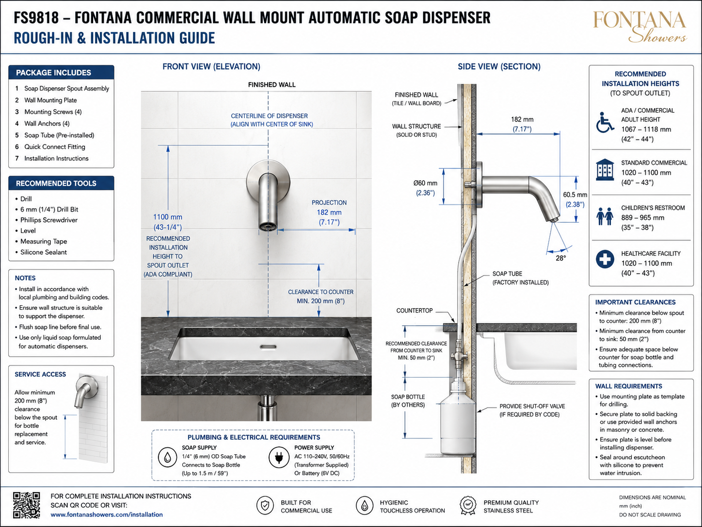
Fontana Automatic Soap Dispensers™ | Architectural and Engineering Resource
Fontana FS9836DP Deck-Mounted Automatic Soap Dispenser:
Countertop Installation Drawing
This countertop installation drawing resource supports architects, plumbing
engineers, interior designers, contractors, millwork fabricators, installers
and facility managers coordinating the Fontana FS9836DP deck-mounted automatic
soap dispenser within commercial washrooms. The drawing explains how the
dispenser passes through the countertop, how its mounting components are
assembled and how the concealed soap and electrical components should be
arranged below the counter.
Fontana FS9836DP Deck-Mounted Automatic Soap Dispenser
The Fontana FS9836DP is a commercial automatic soap dispenser designed
for installation through a prepared countertop opening. Its above-counter
spout provides touch-free soap delivery while the threaded mounting shank,
soap tube, pump, reservoir and power components remain concealed inside
the vanity or millwork cabinet.
- Model: FS9836DP
- Product type: Automatic soap dispenser
- Installation: Deck mounted
- Mounting location: Countertop or lavatory deck
- Operation: Touch-free sensor activation
- Soap supply: Concealed under-counter reservoir
- Service access: From below the countertop
- Application: Commercial and institutional washrooms
Countertop Installation Drawing Scope
The countertop installation drawing should include a side-section view
through the dispenser, mounting deck and under-counter assembly. Dimensions
should be referenced from the finished countertop surface, centerline of the
mounting opening and soap outlet. Metric and imperial measurements should be
shown wherever verified product dimensions are available.
Countertop Section View
Shows the dispenser installed through the countertop in cross-section.
The drawing should identify the above-counter spout, mounting base,
gasket, countertop, threaded shank, washer, retaining nut, soap tube
and electrical cable. This provides installers with a complete view
of how the product is secured to the deck.
Countertop Opening
Identifies the required mounting-hole diameter and its permitted
tolerance. The hole should be centered at the approved installation
location and drilled perpendicular to the finished surface. Final
opening dimensions must be verified from the approved FS9836DP
specification or installation documentation.
Maximum Counter Thickness
Shows the permitted countertop thickness that can be accommodated by
the dispenser’s threaded mounting shank. The drawing should allow
enough exposed thread below the deck for the washer and retaining nut
to engage securely without interfering with tubing or electrical
connections.
Mounting Base and Gasket
Illustrates the relationship between the dispenser base, sealing
gasket and finished countertop. The gasket should sit evenly beneath
the base to help stabilize the dispenser and limit water intrusion
through the mounting opening.
Washer and Retaining Nut
Shows the washer and mounting nut beneath the countertop. The washer
should remain flat against the underside of the deck while the nut is
tightened sufficiently to secure the dispenser without damaging stone,
quartz, solid-surface material or laminated millwork.
Spout Reach and Outlet Position
Identifies the horizontal projection from the dispenser centerline or
mounting base to the soap outlet. The outlet should be positioned over
the usable capture area of the lavatory so dispensed soap falls inside
the basin rather than onto the countertop or backsplash.
Sensor Location and Activation Area
Locates the infrared sensor and illustrates the intended hand-detection
area beneath the soap outlet. The sensor path should remain clear of
the basin rim, raised backsplash, reflective trim and accessories that
could obstruct detection or cause unintended activation.
Under-Counter Soap Tube
Shows the soap tube extending downward from the dispenser shank toward
the pump and reservoir. Tubing should follow a smooth route without
sharp bends, crushing, excessive tension or contact with cabinet
hardware that could restrict soap movement.
Electrical Cable Routing
Identifies the concealed cable path between the sensor dispenser,
control module, pump and approved power source. Wiring should be kept
clear of wet areas, sharp edges, moving cabinet components and routine
soap-reservoir removal paths.
Soap Reservoir Position
Shows the reservoir below the countertop and within practical reach
of maintenance personnel. The container should remain upright,
accessible for refilling and positioned so its tube connection is not
kinked or stretched.
Counter Edge Clearance
Defines the recommended space between the dispenser mounting
centerline and the front or rear counter edge. Adequate clearance is
required to accommodate the mounting nut, hand tools, soap tubing and
nearby lavatory components below the deck.
Backsplash Clearance
Shows the horizontal separation between the rear of the dispenser and
the backsplash or finished wall. This space should permit cleaning,
installation tool access and removal of the dispenser body when
maintenance is required.
Faucet-to-Dispenser Spacing
Coordinates the soap dispenser with the adjacent faucet. Sufficient
spacing should be maintained between mounting holes, escutcheons,
threaded shanks, supply hoses, sensor cables and concealed components
below the countertop.
Service Clearance
Defines the unobstructed area required below the counter for tightening
the mounting hardware, disconnecting the soap tube, servicing the pump,
accessing the controller and removing the reservoir for cleaning or
refilling.
Finished Installation Detail
Shows the complete installed configuration with the spout above the
counter, the outlet aligned over the lavatory and the reservoir, pump,
controller, tubing and power connections organized below the deck.
Engineering note: Do not use estimated mounting-hole,
counter-thickness, projection or clearance dimensions in construction
documents. Confirm all final measurements from the approved FontanaShowers
specification sheet, installation instructions or project submittal before
drilling the countertop.
Recommended Countertop Installation Sequence
1. Confirm the Location
Coordinate the dispenser centerline with the lavatory, faucet,
backsplash and under-counter cabinet components. Verify that the soap
outlet will discharge into the basin’s usable area.
2. Verify the Countertop
Confirm the deck material, thickness and structural condition. The
surface should be rigid, level and suitable for drilling without
cracking, delamination or unsupported movement.
3. Prepare the Opening
Mark the approved centerline and create the mounting opening using
the correct tool for the countertop material. Remove debris and protect
the finished surface from chipping or scratching.
4. Install the Gasket
Place the supplied gasket beneath the dispenser base. Ensure it lies
flat and remains centered around the mounting opening before inserting
the threaded shank.
5. Insert the Dispenser
Feed the threaded shank, soap tube and sensor cable through the
countertop opening. Orient the soap outlet toward the center of the
lavatory before securing the assembly.
6. Secure the Mounting Hardware
Install the underside washer and retaining nut. Hold the dispenser in
its correct orientation while tightening the nut evenly. Do not
over-tighten against stone or brittle countertop materials.
7. Connect the Soap Tube
Route the soap tube to the pump or reservoir connection. Keep the path
smooth, shorten only where permitted and verify that all connections
are fully seated.
8. Connect the Control Components
Connect the sensor, pump, controller and approved power source
according to the product instructions. Keep electrical connections
dry, supported and accessible for future servicing.
9. Install the Soap Reservoir
Position the reservoir upright below the dispenser. Provide enough
clearance to remove its cap, disconnect the tube and withdraw the
container without disturbing plumbing or cabinet hardware.
10. Prime and Test
Fill the reservoir with compatible soap, prime the pump and test
several activation cycles. Confirm consistent dispensing, accurate
sensor response and correct soap delivery into the basin.
Architectural and MEP Coordination Considerations
Lavatory Alignment
Align the soap outlet with the basin’s usable capture area to reduce
soap residue on the counter, backsplash and floor.
Countertop Fabrication
Include the verified dispenser opening in countertop shop drawings and
coordinate it with faucet holes, sink clips, seams and structural
supports.
Undermount Sink Clearance
Check for conflicts between the dispenser shank and the sink rim,
mounting rails, clips, adhesive supports or reinforcing brackets beneath
the counter.
Accessible Reach
Coordinate the dispenser location and sensor activation area with the
accessible lavatory approach and applicable reach-range requirements.
Power Coordination
Confirm the specified power arrangement and coordinate the controller,
transformer, receptacle or battery compartment with the electrical
drawings.
Service Access
Preserve access to the mounting nut, soap tube, pump, controller,
reservoir and power components without removing permanent millwork.
Countertop Installation Drawing Requirements
-
Front elevation:
Show the dispenser centered in relation to the lavatory and indicate the
soap outlet, sensor position and finished countertop.
-
Side section:
Show the spout, countertop, gasket, threaded shank, washer, retaining nut,
tube, cable and under-counter reservoir.
-
Top plan:
Show the mounting centerline, base footprint, outlet direction, faucet
spacing and relationship to the lavatory opening.
-
Mounting-hole detail:
Provide the verified hole diameter, tolerance and countertop-thickness
requirement.
-
Clearance detail:
Identify counter-edge, backsplash, basin, faucet and under-counter service
clearances.
-
Dimension format:
Provide verified measurements in millimeters and inches with consistent
dimension arrows, centerlines and leader notes.
-
Component identification:
Label the dispenser body, sensor, soap outlet, gasket, shank, washer,
retaining nut, tube, pump, reservoir, controller and power source.
-
Drawing notes:
Include installation warnings, verification requirements, scale notation,
model number and revision information.
FontanaShowers Installation and Specification Resources
Professional Engineering and Accessibility References
-
American Institute of Architects
— professional architectural authority supporting coordinated restroom
design, construction documentation, millwork detailing and fixture
specification.
-
American Society of Plumbing Engineers
— technical authority supporting plumbing-system engineering, fixture
coordination, concealed service planning and commercial washroom
specification.
-
U.S. Access Board – Building Blocks
— accessibility guidance covering operable parts, clear floor space,
reach ranges and accessible fixture coordination.
-
U.S. Access Board – Lavatories and Sinks Guide
— explains accessible lavatory clearances, approach, reach and accessory
coordination under the ADA Standards.
-
International Facility Management Association
— internationally recognized authority for facility operations,
maintenance access, lifecycle planning and commercial building performance.
-
OSHA – Restroom and Sanitation Requirements
— workplace guidance concerning sanitary restrooms, handwashing facilities
and access to soap.
Project verification: This countertop installation drawing is
a coordination resource and does not replace an approved project submittal. The
architect, engineer, countertop fabricator and licensed installer should verify
final product dimensions, mounting-hole diameter, deck thickness, clearances,
power requirements, accessibility criteria and locally adopted codes before
fabrication or installation.
|
|
|