Fontana Automatic Soap Dispensers™ | Architectural and Engineering Resource
Fontana FS9836DP Deck-Mounted Automatic Soap Dispenser:
Cross-Section Installation Detail
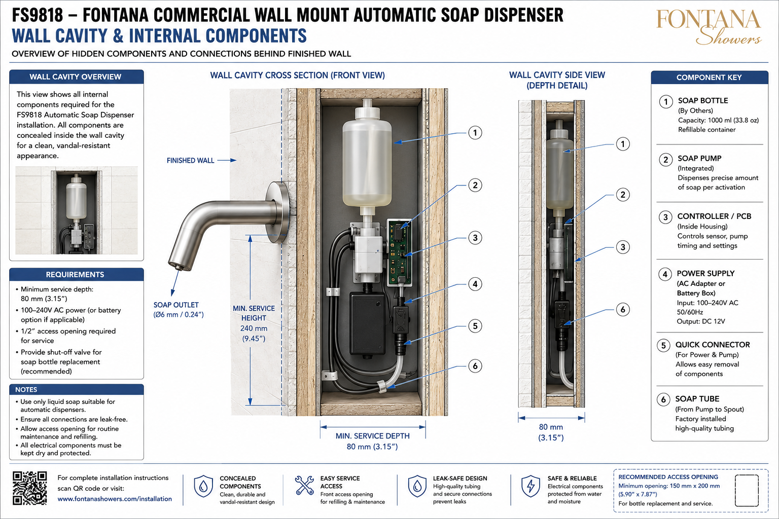
This cross-section installation resource supports architects, plumbing
engineers, electrical engineers, interior designers, countertop fabricators,
contractors, installers and facility managers coordinating the Fontana
FS9836DP deck-mounted automatic soap dispenser within commercial washrooms.
The drawing shows the complete sectional relationship between the visible
dispenser spout, finished countertop, mounting hardware, soap tube, sensor
cable, pump, controller, power components, soap reservoir and surrounding
cabinet construction.
Fontana FS9836DP Deck-Mounted Automatic Soap Dispenser
The Fontana FS9836DP is a commercial touchless soap dispenser designed
for installation through a countertop or lavatory deck. The visible
spout and sensor remain above the finished surface while the threaded
shank, mounting hardware, tubing, pump, controller, power source and
soap reservoir are concealed inside the cabinet below.
- Model: FS9836DP
- Product type: Automatic soap dispenser
- Installation: Deck mounted
- Operation: Touch-free infrared sensor
- Mounting location: Countertop or lavatory deck
- Soap supply: Concealed under-counter reservoir
- Internal components: Pump, controller, tubing and power supply
- Application: Commercial and institutional washrooms
Cross-Section Installation Drawing Scope
The cross-section drawing should cut through the dispenser mounting
centerline and show every component from the soap outlet above the
countertop to the reservoir and control equipment below. The drawing should
clearly identify material layers, mounting interfaces, tubing routes,
electrical connections, component clearances and service-access zones.
Dimensions should be shown in millimeters and inches only where verified
manufacturer data is available.
Section A-A Through Dispenser Centerline
Shows a vertical section through the center of the dispenser,
countertop opening and threaded shank. The view should identify the
spout body, sensor, outlet, base, gasket, finished countertop,
mounting washer, retaining nut, soap tube and sensor cable.
Section B-B Through Cabinet Interior
Shows the concealed under-counter assembly from the front or side,
including the reservoir, pump, controller, transformer or battery
box, electrical connectors, cable clips and tubing connections.
Dispenser Spout Assembly
Identifies the visible spout body and its orientation over the
lavatory. The drawing should distinguish the outer housing, soap
outlet, sensor window and mounting base without altering the actual
product geometry.
Soap Outlet Detail
Locates the soap discharge opening at the underside of the spout.
The outlet should be shown directing soap toward the usable basin
area rather than the countertop, backsplash or outer edge of the
lavatory.
Sensor Window
Shows the infrared sensor location and its relationship to the soap
outlet. The section should indicate that the sensor field must remain
clear of the basin rim, reflective accessories and other projecting
surfaces.
Mounting Base
Shows the dispenser base resting on the finished countertop. The
base should remain level, fully supported and correctly oriented
toward the basin before the underside mounting hardware is tightened.
Sealing Gasket
Illustrates the gasket positioned between the dispenser base and the
finished countertop. The gasket helps stabilize the assembly and
reduce water entry through the mounting opening.
Finished Countertop
Identifies the countertop material and thickness. The sectional view
should show the complete finished deck, including any build-up layer,
substrate or reinforcement affecting the threaded mounting length.
Mounting Opening
Shows the prepared countertop opening centered beneath the dispenser
base. Final hole diameter and tolerance must be taken from approved
FontanaShowers product documentation before fabrication.
Threaded Mounting Shank
Displays the threaded shank passing vertically through the countertop.
Sufficient thread should remain below the deck to accommodate the
washer, retaining nut and connected tubing without interference.
Underside Mounting Washer
Shows the washer seated flat against the underside of the countertop.
It distributes mounting pressure and provides a stable bearing surface
for the retaining nut.
Retaining Nut
Identifies the nut securing the dispenser beneath the deck. It should
be tightened evenly while maintaining correct spout alignment and
without damaging brittle or layered countertop materials.
Soap Tube Connection
Shows the soap tube connected to the dispenser shank or internal
outlet fitting. The connection should be fully seated, leak-free and
accessible for inspection or replacement.
Soap Tube Routing
Illustrates the complete tube route from the dispenser to the pump
and reservoir. The path should remain smooth and free of kinks,
compression, excessive loops or sharp directional changes.
Sensor Cable
Shows the low-voltage sensor cable passing below the countertop and
connecting to the controller. The cable should be supported and kept
clear of plumbing fittings, cabinet hardware and sharp edges.
Soap Reservoir
Identifies the refillable soap container within the cabinet. The
reservoir should remain upright, below the dispenser and accessible
for refilling, cleaning and removal.
Reservoir Cap and Pickup Connection
Shows the upper reservoir connection, cap and soap pickup arrangement.
The connection should remain sealed while permitting the container to
be opened or removed during maintenance.
Soap Pump
Locates the pump between the reservoir and dispenser outlet. The
pump should be securely supported and installed in the approved
orientation to provide consistent measured dispensing.
Controller or PCB Housing
Shows the electronic controller that receives the sensor signal and
operates the pump. The housing should be mounted in a dry location
with clear access to connectors and adjustment controls.
Power Supply
Identifies the approved AC adapter, transformer or battery box.
The power component should remain protected from water, plumbing
leaks, cleaning liquids and contact with the cabinet floor.
Quick Connectors
Shows the removable electrical or pump connectors between system
components. Quick connectors should remain visible and accessible
for commissioning, troubleshooting and replacement.
Cable Management Clips
Identifies clips or supports used to organize wiring and tubing.
They should prevent loose cables from contacting drain piping,
cabinet hinges, drawer slides or reservoir-removal paths.
Cabinet Side Wall
Shows the adjacent millwork panel or enclosure supporting concealed
components. Fasteners should not penetrate plumbing, electrical
wiring or the soap reservoir.
Cabinet Floor
Identifies the lower cabinet surface beneath the equipment. Electrical
components should be elevated above areas where cleaning water or
leakage could collect.
Minimum Service Height
Shows the vertical space required for reservoir removal, pump access,
tube servicing and electrical inspection. The service envelope should
remain unobstructed after installation of the sink and drain.
Minimum Service Depth
Defines the cabinet depth required for the reservoir, controller,
pump, wiring and tubing. Adequate depth should allow components to be
removed toward the cabinet access opening.
Front Service Access
Shows the clear maintenance opening required in front of concealed
components. Access should permit refilling, priming, inspection and
replacement without removing permanent countertop or plumbing work.
Completed Cross-Section Assembly
Presents the full installed configuration from the soap outlet to the
reservoir. Every concealed component should be labelled and arranged
to support reliable operation and practical long-term maintenance.
Engineering note: Do not insert estimated dimensions for
the mounting opening, countertop thickness, spout projection, component
depth, reservoir size or cable length into project drawings. Verify all
final measurements and electrical requirements using the approved
FontanaShowers specification sheet, installation instructions or project
submittal package.
Required Cross-Section Drawing Views
Section A-A: Dispenser Centerline
Show the soap outlet, sensor, spout, base, gasket, countertop,
threaded shank, washer, nut, soap tube and sensor cable.
Section B-B: Cabinet Front View
Show the reservoir, pump, controller, power source, tubing,
connectors and cable-management arrangement.
Section C-C: Cabinet Depth Detail
Show the available cabinet depth, component projection, sink-bowl
clearance and front removal path.
Countertop Penetration Detail
Show the dispenser base, gasket, verified mounting opening, deck
thickness, mounting shank, washer and retaining nut.
Internal Connection Detail
Show the soap tube, pump connection, controller plugs, sensor cable,
power connector and component identification.
Service Envelope Detail
Show the minimum access height, depth, width and reservoir-removal
direction required for routine maintenance.
Cross-Section Installation Requirements
Secure Countertop Support
The deck must be rigid, level and capable of supporting the
dispenser without movement, cracking or delamination.
Leak-Resistant Connections
All soap tube and reservoir connections should be fully seated and
checked for leakage before the cabinet is closed.
Dry Electrical Zone
The controller, transformer, battery box and connectors should be
kept away from the drain, shutoff valves and potential leak points.
Accessible Reservoir
The soap container should be positioned so it can be refilled and
removed without disconnecting unrelated plumbing components.
Supported Tubing
Soap tubing should be clipped or guided to prevent sagging, kinking
or contact with moving cabinet hardware.
Protected Wiring
Low-voltage cables should be routed away from sharp edges, heat,
standing moisture and service paths.
Sink-Bowl Clearance
The mounting shank, reservoir and controller should remain clear of
the underside of the basin and its mounting hardware.
Serviceable Layout
Components should be arranged so individual parts can be inspected
or replaced without removing the countertop or lavatory.
Recommended Cross-Section Installation Sequence
1. Verify the Approved Drawing
Confirm the model, countertop opening, deck thickness, component
layout and power arrangement before installation.
2. Prepare the Countertop
Create the verified mounting opening and clean the surrounding
surface before inserting the dispenser.
3. Position the Gasket
Place the sealing gasket beneath the dispenser base and align it
with the mounting opening.
4. Insert the Spout Assembly
Feed the threaded shank, soap tube and sensor cable through the
countertop while orienting the outlet toward the basin.
5. Secure the Dispenser
Install the underside washer and retaining nut and tighten evenly
without overloading the countertop.
6. Mount the Controller
Fix the control housing in a dry and accessible cabinet location
within the permitted sensor-cable reach.
7. Position the Reservoir and Pump
Install the soap container upright and connect the pump in the
approved orientation.
8. Connect the Soap Tube
Route and connect the tubing without sharp bends or excessive
length, then check every fitting.
9. Connect Sensor and Power
Attach the sensor, pump and power connectors to the controller and
secure excess cable with suitable clips.
10. Prime and Inspect
Fill the reservoir, prime the pump, test multiple dispensing cycles
and inspect all soap connections for leakage.
Architectural and MEP Coordination Considerations
Countertop Fabrication
Coordinate the verified dispenser opening with the sink cutout,
faucet holes, seams, substrate and structural reinforcement.
Lavatory Alignment
Position the outlet over the basin while maintaining adequate
under-counter clearance from the sink rim and mounting clips.
Plumbing Separation
Keep electrical and soap components clear of the drain, trap,
supply hoses and shutoff valves.
Electrical Coordination
Confirm voltage, transformer, receptacle or battery requirements
with the project electrical drawings.
Cabinet Coordination
Avoid conflicts with shelves, drawers, partitions, hinges,
reinforcing rails and removable access panels.
Facility Maintenance
Provide practical access for soap refilling, tube cleaning, pump
replacement, controller testing and power servicing.
FontanaShowers Installation and Specification Resources
Professional Engineering and Accessibility References
Project verification: This cross-section installation detail
is intended for architectural, plumbing and electrical coordination and does
not replace an approved project submittal. The architect, engineer,
countertop fabricator, electrical contractor and licensed installer should
verify final dimensions, materials, mounting hardware, tubing limits, power
requirements, service clearances, accessibility criteria and locally adopted
codes before fabrication or installation.
|
|
|