Architectural and Engineering Technical Resource
Touchless Automatic Faucets & Soap Dispensers Technical Drawing Options in Stainless Steel
A dimensional drawing is the primary coordination document connecting a
touchless fixture with the lavatory, countertop, plumbing rough-in,
electrical supply and maintenance area. For commercial projects, automatic
faucets and soap dispensers should be documented as one coordinated
handwashing system rather than as separate decorative products.
Read More
Show Less
FontanaShowers’ architect and specifier resources provide access to
specification-ready BIM, CAD and technical submittal information.
Available documentation may include Revit families, AutoCAD files,
IFC models, technical PDFs, installation guides and product-specific
cut sheets, depending on the selected fixture and project request.
These resources help architects, plumbing engineers, BIM
coordinators and contractors verify fixture placement, deck
penetrations, sensor clearances, power requirements and service
access before fabrication or installation begins.

A professional AEC submittal should present the fixture clearly
from every angle needed for architectural, plumbing and maintenance
coordination.
-
Front and side elevations:
Confirm overall height, body width, sensor position, spout
reach, outlet angle and countertop clearance.
-
Plan and mounting views:
Verify base dimensions, drilling locations, edge clearances and
faucet-to-dispenser spacing.
-
Below-deck service diagram:
Identify valves, control boxes, power supplies, tubing,
reservoirs and maintenance access.
Read More
Show Less
A coordinated reflected countertop plan should identify the
centerline of the faucet, soap dispenser and basin, together
with the backsplash, mirror line and all required deck
penetrations.
The below-deck drawing should show solenoid valves, control
modules, electrical connections, power supplies, soap
reservoirs, delivery tubing, mixing valves, isolation valves
and the clear working space required for future servicing.
This level of documentation is particularly important for
multi-user wash stations, where structural supports, sensor
fields, water supplies, electrical components and
maintenance routes may overlap.
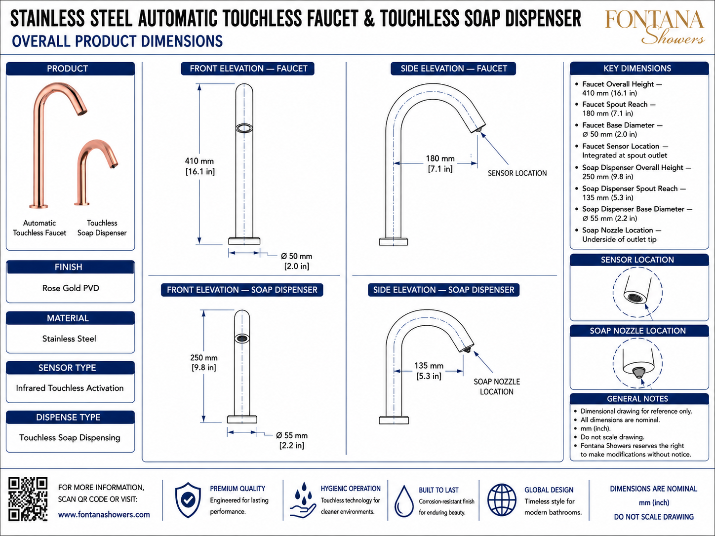
Key Product Dimensions
Every technical drawing should identify the dimensions that directly
affect installation, usability and long-term service access.
Overall Fixture Height
Shown in front and side elevations to check mirror, shelf,
backsplash and visual clearances.
Spout Reach
Shown in the side elevation to position the water discharge
within the basin’s intended wet zone.
Base Diameter
Shown in plan and mounting details to confirm drilling,
escutcheon coverage and the sealing surface.
Faucet Sensor Position
Shown in front and side views to establish the user detection
zone and reduce reflective interference.
Soap Nozzle Position
Shown in front and side elevations to direct soap into the
intended handwashing area.
Fixture Centerlines
Shown in plan view to align the faucet, dispenser, basin and
countertop penetrations.
Faucet-to-Dispenser Spacing
Shown in plan view to limit sensor overlap and support an
intuitive washing sequence.
Below-Deck Service Depth
Shown in section details to protect space for controls, valves,
tubing, wiring and reservoirs.
Dimensional Control Note
The manufacturer-approved cut sheet remains the dimensional
authority. Never scale product photographs, renderings or BIM
preview images.
Coordination note:
Confirm fixture projection, basin geometry, sensing range, deck
drilling and maintenance access before countertop fabrication.
Read More
Show Less
The technical sheet should also identify power requirements,
soap routing, service clearances and the relationship between
the sensor and nearby reflective surfaces. Early verification
can reduce false activation, drilling errors and inaccessible
components.
Drawing Scale: Millimetres and Inches
Primary Measurement Format
Use millimetres as the controlled measurement, with inches in
brackets where U.S. project teams require both systems.
Dual-Unit Example
Present a controlled dimension as
250 mm (9.84 in).
Exact Conversion
Use the exact relationship:
1 inch = 25.4 millimetres.
Controlled Rounding
Calculate the secondary unit from one approved dimension rather
than rounding metric and imperial values separately.
Recommended Drawing Scales
Use 1:5 or 1:10 for elevations, 1:2 for mounting details and 1:20
for lavatory coordination plans.
Printed-Sheet Control
Add “Do Not Scale Drawing—Use Figured Dimensions” and label each
value as nominal, minimum, maximum or field verified.
Read More
Show Less
Dual-unit documentation is most reliable when one measurement
system controls the design and the second is treated as a
converted reference. This prevents conflicting values between
architectural sheets, plumbing documents, fabrication drawings
and installation instructions.
Because a PDF may be enlarged, reduced or printed on a different
sheet size, each drawing should include a graphical scale bar and
a clear instruction to use written dimensions rather than the
printed image scale.
AEC Coordination Case Study
Read More
Show Less
This case demonstrates why touchless fixture submittals should
be reviewed as a complete MEP-ready package. The approval set
should include product cut sheets, BIM or CAD files, wiring
diagrams, flow information, installation instructions and
relevant compliance documentation.
Coordinating these materials before fabrication reduces RFIs,
limits countertop rework and gives the facilities team a clear,
serviceable arrangement after the washroom is operational.
Specification and Authority Requirements
Read More
Show Less
Touchless faucet schedules are generally coordinated with
Division 22 plumbing requirements, while soap-dispenser
assemblies may also intersect Division 10 accessory
specifications.
The project documentation should identify flow rate, operating
pressure, power method, sensor range, BIM parameters, installation
requirements and maintenance criteria. Fixture selection should
also be checked against the applicable plumbing-fitting standard,
local codes and project accessibility criteria.
Automatic activation reduces the need for manual contact, but it
does not replace verification of accessible reach, basin
clearances, approach geometry or component placement.
Technical coordination summary:
A complete drawing package converts touchless fixtures into buildable,
reviewable and maintainable assemblies. Controlling fixture height, spout
reach, mounting dimensions, sensor placement, soap delivery, service zones
and dual-unit measurements can reduce RFIs, prevent countertop rework and
support a coordinated commercial handwashing system.
|
|
|