Fontana Wall-Mounted Sensor Faucets™ | Architectural and Engineering Resource
Fontana FS8014ORB Oil Rubbed Bronze Wall-Mounted Automatic Sensor Faucet:
Cold-Water Configuration
This cold-water-configuration resource is intended to support architects,
plumbing engineers, electrical engineers, interior designers, contractors,
installers and facility managers coordinating a dedicated cold-water-only
installation for the Fontana FS8014ORB wall-mounted automatic sensor faucet.
The drawing package should identify the cold-water supply, shutoff valve,
strainer, solenoid valve, control module, faucet connection, supply direction,
service access and required connection sizes.

Fontana Oil Rubbed Bronze Wall-Mounted Automatic Sensor Faucet
The Fontana FS8014ORB wall-mounted faucet may be coordinated with a
dedicated cold-water valve-kit arrangement in which the incoming cold
water supply passes through an accessible shutoff valve, inline strainer
and solenoid valve before serving the faucet through a flexible supply
connection. The control module and power supply should be located within
an accessible service zone so the system can be commissioned, maintained
and serviced without disturbing finished surfaces.
-
Model:
FS8014ORB
-
Installation:
Wall mounted with concealed cold-water valve kit
-
Finish:
Oil rubbed bronze
-
Material:
Solid brass trim spout
-
Fixture type:
Automatic sensor faucet
-
Water supply:
Dedicated cold-water line
-
Service valve:
1/2-inch shutoff valve
-
Strainer:
Inline Y-type strainer
-
Control valve:
1/2-inch solenoid valve
-
Flexible hose:
1/2-inch supply hose
-
Faucet connection:
1/2-inch NPT connection, as coordinated
-
Service requirement:
Accessible control module and service opening required
Required Cold-Water Configuration Drawing Package
Each drawing should use a consistent line hierarchy, component numbering
system and product-identification block. The cold-water-only configuration
should clearly indicate the operational sequence from the dedicated building
cold-water supply to the faucet trim, with separate notation for electrical
control connections, service-access components and the required connection
sizes. Flow direction should be clearly shown so installers can coordinate
the system without ambiguity.
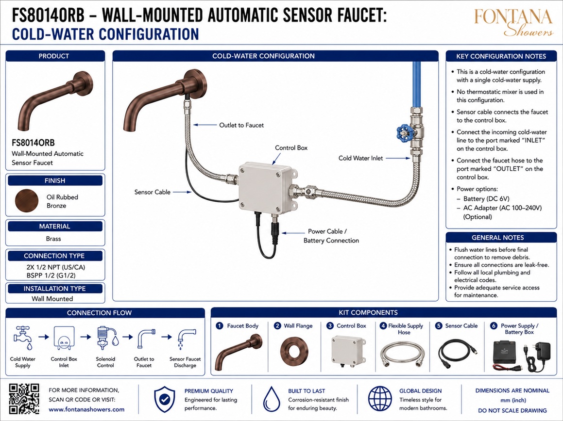
Typical Cold-Water Configuration
Shows the complete cold-water-only arrangement serving the
Fontana FS8014ORB automatic sensor faucet. The drawing should
illustrate the cold-water supply entering the shutoff valve,
passing through the strainer and solenoid valve, continuing through
the flexible supply hose to the faucet connection, and linking the
control module to the solenoid and power source within an accessible
service area.
Cold-Water Supply
Identifies the dedicated building cold-water supply line serving
the faucet assembly. The drawing should show the supply entering
the concealed valve-kit layout from the upstream branch and moving
in the intended direction toward the service valve and downstream
operating components.
Shutoff Valve and Strainer
Documents the service shutoff valve followed by the inline strainer.
The shutoff valve allows local isolation for maintenance, while the
strainer helps protect the solenoid valve and faucet from debris,
scale and construction residue. Both components should remain
accessible for operation and cleaning.
Solenoid Valve
Shows the electrically controlled solenoid valve located downstream
of the strainer. The solenoid opens when activated by the control
module and should be installed in the correct flow direction. Its
position should allow service access for inspection, replacement and
connection testing.
Control Module
Identifies the electronic control module that receives the sensor
signal and actuates the solenoid valve. The module should be mounted
in a dry, protected and accessible service zone with clear routing to
the sensor, solenoid and power supply. Electrical connections should
be shown distinctly from the water path.
Faucet Connection and Supply Direction
Defines the flexible supply hose and final faucet connection serving
the wall-mounted spout trim. The drawing should identify the direction
of supply flow from the building connection toward the faucet inlet
and should show the final connection size used at the faucet body or
spout assembly.
Service Access
Shows the required access area or service panel for the concealed
valve kit. The opening should be large enough to reach the shutoff
valve, strainer, solenoid, flexible hose, control module and power
connection for routine maintenance, troubleshooting and replacement.
Connection Sizes
Summarizes the principal connection sizes used within the cold-water
layout. The drawing should identify water-service connections,
strainer and solenoid sizes, flexible-hose connections and the faucet
inlet designation. Connection sizes should be confirmed against the
approved valve kit and current product documentation before rough-in.
Engineering note:
The cold-water-only arrangement shown is a typical coordination layout.
Actual valve-kit components, service-opening size, hose length, electrical
supply arrangement and exact connection designations may vary according to
the selected FontanaShowers control package. Flush the supply line before
final connection and verify all component compatibility against the approved
product submittal and installation instructions.
Plumbing, Electrical and Service Coordination Considerations
Cold-Water Source Verification
Confirm that the designated cold-water branch is the correct supply
for the faucet and that local code requirements for temperature and
fixture application are satisfied before installation.
Local Isolation
Locate the shutoff valve where it can be reached easily through the
service opening so maintenance staff can isolate the faucet without
shutting down adjacent fixtures.
Strainer Access
Provide adequate clearance to remove and clean the strainer. Inspect
the strainer after startup and during preventive maintenance to reduce
the risk of low flow or valve fouling.
Control-Module Placement
Mount the control module in a dry and protected service zone with
clear access for wiring, inspection and replacement. Keep cables
and power connections separated from water-service interference.
Flexible-Hose Routing
Route the hose without tight bends, kinks or abrasion points.
Maintain sufficient slack for installation and future servicing while
keeping the hose clear of sharp framing edges and electrical devices.
Connection-Size Confirmation
Verify shutoff-valve, strainer, solenoid, hose and faucet connection
sizes before procurement and rough-in. Use the approved valve-kit
submittal as the governing reference for final connection details.
FontanaShowers Installation and Specification Resources
FS8014ORB Product Page
Product information, oil rubbed bronze finish details, technical
specifications and available documentation for the Fontana
FS8014ORB wall-mounted faucet.
FontanaShowers Installation Hub
Central installation information for wall-mounted faucets,
automatic sensor faucets, concealed valve kits and related
FontanaShowers fixtures.
Commercial Touchless Faucet Collection
Explore related automatic faucet configurations, sensor controls
and concealed operating assemblies for commercial restroom projects.
Faucet BIM and Coordination Resources
Architectural and engineering resources supporting fixture
selection, valve-kit planning and multidisciplinary project
documentation.
Valve-Kit Installation Resources
General installation information covering supply flushing,
strainers, solenoid valves, control modules, service access,
testing and commissioning.
Fontana Bathroom Faucet Collection
View related wall-mounted and sensor-operated bathroom-faucet
options for coordinated commercial and hospitality fixture
selection.
Professional Engineering and Accessibility References
Project verification:
Cold-water-configuration drawings are coordination tools and do not replace
approved project submittals. The architect, plumbing engineer, electrical
engineer, contractor and licensed installer should verify the cold-water
supply, shutoff valve, strainer, solenoid valve, control module, faucet
connection, supply direction, service access, connection sizes, power
arrangement, accessibility requirements and locally adopted codes before
installation and commissioning.
|
|
|