Fontana Wall-Mounted Sensor Faucets™ | Architectural and Engineering Resource
Fontana FS8014ORB Oil Rubbed Bronze Wall Mounted Automatic Sensor Faucet:
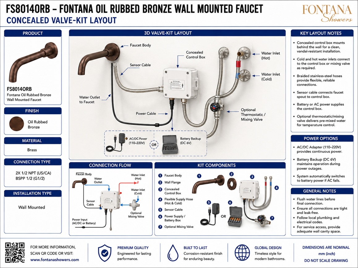
Concealed Valve-Kit Layout
This concealed valve-kit layout resource is intended to support architects,
plumbing engineers, electrical engineers, interior designers, contractors,
installers and facility managers coordinating the concealed operating assembly
for the Fontana FS8014ORB wall-mounted automatic sensor faucet. The layout
should show the trim spout connected to the required valve kit, including the
sensor faucet spout, sensor cable, solenoid valve, electronic control module,
water inlet, water outlet, shutoff valve, strainer, flexible hose, power
source and service access panel.

Fontana Oil Rubbed Bronze Wall Mounted Automatic Sensor Faucet
The Fontana FS8014ORB concealed sensor-faucet arrangement combines the
exposed wall-mounted trim spout with a concealed valve-kit assembly
located within an accessible service cavity or panel. The concealed
layout coordinates electronic activation, water control, power supply
and maintenance access while preserving a clean architectural appearance
at the finished wall.
-
Model:
FS8014ORB
-
Installation:
Wall mounted with concealed valve kit
-
Finish:
Oil rubbed bronze
-
Material:
Solid brass trim spout
-
Fixture type:
Automatic sensor faucet
-
Trim component:
Sensor faucet spout
-
Electronic components:
Sensor cable, control module and solenoid valve
-
Water pathway:
Water inlet, strainer, shutoff valve, flexible hose and outlet
-
Power source:
Transformer or approved power pack, as specified
-
Service requirement:
Accessible service access panel required
-
Application:
Commercial and institutional restrooms
-
Coordination:
Plumbing and electrical trade coordination required
Required Concealed Valve-Kit Layout Drawing Package
Each drawing should use a consistent scale, line hierarchy and product
identification block. The concealed layout should clearly distinguish the
exposed trim spout from the hidden valve-kit components located inside the
service cavity or access panel. Water flow direction, wiring paths, control
components, shutoff devices and maintenance clearances should be clearly
labeled so the plumbing and electrical teams can coordinate installation,
testing and servicing.
Standard Concealed Valve-Kit Layout
Shows the complete concealed operating layout for the Fontana
FS8014ORB sensor faucet, including the exposed spout trim, sensor
cable, electronic control module, solenoid valve, water inlet,
shutoff valve, strainer, flexible hose, outlet connection and
power source within an accessible service panel. This drawing
provides the primary coordination reference for concealed
plumbing and electrical installation.
Sensor Faucet Spout
Identifies the exposed wall-mounted trim spout and its relationship
to the finished wall and concealed service cavity. The spout should
be shown as the visible fixture connected to the concealed valve kit
through the designated outlet connection and sensor cable path.
Sensor Cable
Shows the cable linking the sensor faucet spout to the electronic
control module. The drawing should indicate a protected cable route
that avoids sharp edges, moisture traps, excessive heat and service
conflicts while allowing connection and disconnection for maintenance.
Solenoid Valve and Control Module
Documents the electronic control module and solenoid valve that
operate the faucet automatically. The control module should be shown
in an accessible, protected location within the service cavity, with
clear connections to the sensor cable, power source and valve.
Water Inlet and Water Outlet
Identifies the incoming building water supply and the outlet path
leading from the concealed valve assembly to the faucet spout. Flow
direction should be clear so installers can distinguish the inlet
side from the controlled outlet serving the trim spout.
Shutoff Valve and Strainer
Shows the shutoff valve and inline strainer positioned ahead of the
control valve assembly. These components should remain accessible for
isolation, cleaning, troubleshooting and routine maintenance without
requiring removal of permanent wall finishes.
Flexible Hose
Identifies the flexible hose connection linking concealed valve-kit
components within the service zone. The hose route should avoid kinks,
compression, abrasion and tight bends, and should be long enough to
permit secure assembly and future service access.
Power Source and Service Access Panel
Defines the power source serving the control module and the service
access panel enclosing the concealed assembly. The access opening
should provide adequate space for inspection, power connection,
solenoid replacement, strainer cleaning and shutoff-valve operation.
Engineering note:
The concealed valve-kit arrangement shown should be treated as a typical
coordination layout. Actual component spacing, service-panel size, hose
lengths, power configuration and control-module location may vary according
to the selected kit and project conditions. Verify all concealed assembly
requirements against the approved FontanaShowers product documentation and
installation instructions before closing the wall or service cavity.
Architectural, Plumbing and Electrical Coordination Considerations
Service Access
Provide an access panel large enough to reach the shutoff valve,
strainer, solenoid valve, control module, hose connections and
power supply without disturbing permanent wall finishes.
Power Coordination
Coordinate the control module and power source with the project
electrical drawings. Provide a protected and serviceable power
connection in accordance with the approved installation method.
Plumbing Flow Direction
Clearly orient the water inlet, outlet, shutoff valve, strainer
and solenoid assembly so the concealed piping route follows the
intended direction of flow to the spout.
Cable and Hose Protection
Route the sensor cable and flexible hose away from sharp edges,
excessive heat, moving parts and overcrowded service spaces to
reduce wear and support long-term reliability.
Valve Isolation and Maintenance
Position the shutoff valve and strainer so they can be operated
and cleaned easily during commissioning and routine maintenance.
Avoid layouts that bury these components behind inaccessible finishes.
Trim and Valve-Kit Compatibility
Verify that the concealed valve kit, spout trim, connection sizes,
power arrangement and control components are compatible before
releasing construction documents or starting rough-in work.
FontanaShowers Installation and Specification Resources
Professional Engineering and Accessibility References
Project verification:
Concealed valve-kit layout drawings are coordination tools and do not replace
approved project submittals. The architect, plumbing engineer, electrical
engineer, contractor and licensed installer should verify the sensor faucet
spout, sensor cable, solenoid valve, electronic control module, water inlet,
water outlet, shutoff valve, strainer, flexible hose, power source,
service-access panel, mounting conditions, accessibility criteria and locally
adopted codes before installation.
|
|
|