Fontana Automatic Sensor Faucets™ | Architectural and Engineering Resource
Fontana American Standard Deck-Mounted Sensor Faucet:
Cold Water Configuration
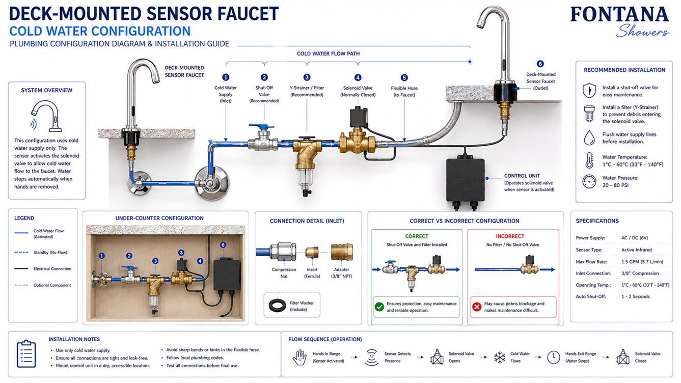
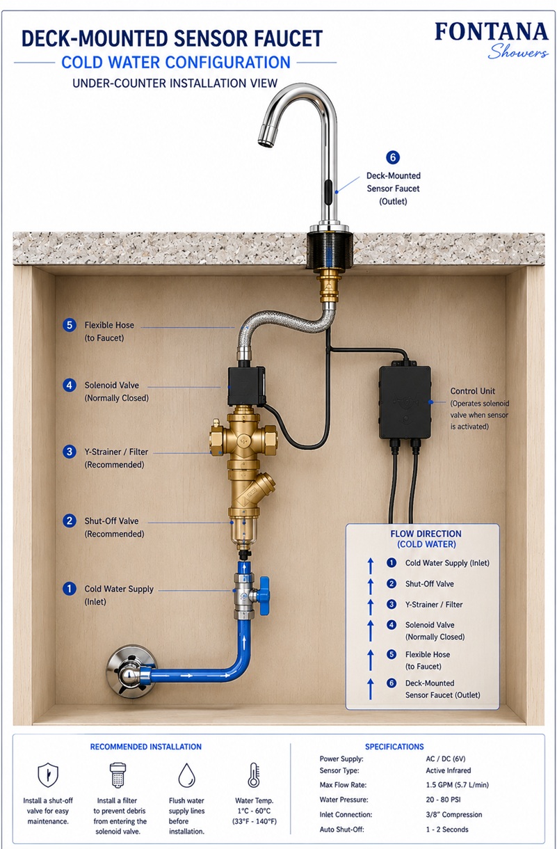
This cold-water configuration resource is intended to support architects,
plumbing engineers, contractors, installers and facility managers
coordinating the Fontana American Standard deck-mounted automatic sensor
faucet with a dedicated cold-water supply. The technical drawing identifies
the building cold-water inlet, accessible service shutoff, filter or
strainer, sensor-controlled solenoid valve, flexible supply connection,
faucet inlet, internal water passage, aerator outlet, flow direction and
required service access.
Fontana American Standard Deck-Mounted Sensor Faucet
The Fontana American Standard Sensor Faucet can be coordinated
with a dedicated cold-water supply for applications where tempered
or mixed-water delivery is not required. In this arrangement,
water travels from the building cold-water line through an
accessible shutoff valve, filtration component and sensor-controlled
solenoid valve before entering the faucet.
When the infrared sensor detects the user’s hands, the control
system opens the solenoid valve and permits cold water to flow
through the faucet body to the aerator outlet. When the hands leave
the detection zone, the solenoid closes and stops water delivery.
Final connection sizes, component positions and flow direction must
be verified from the current product documentation.
-
Model:
FS2361TFDP
-
Installation:
Deck mounted
-
Mounting configuration:
Single hole
-
Finish:
Polished chrome
-
Material:
Brass
-
Faucet type:
Automatic motion-sensor sink faucet
-
Sensor type:
Infrared touchless activation
-
Water configuration:
Dedicated cold-water supply
-
Working pressure:
0.05–0.8 MPa
-
Flow control:
Sensor-operated solenoid valve
-
Supply isolation:
Accessible cold-water shutoff valve
-
Filtration:
Verify the model-specific filter or strainer
-
Outlet:
Aerator-controlled cold-water delivery
Required Cold Water Configuration Drawing Package
Each drawing should use a consistent symbol set, flow-direction arrows
and product-identification block. The drawing package should identify
the dedicated cold-water supply, accessible shutoff valve, filter or
strainer, solenoid valve, flexible supply hose, faucet inlet, internal
water passage and aerator outlet. No hot-water inlet or mixing valve
should be shown within this configuration.
Cold Water Configuration
Shows the complete cold-water route from the building supply
to the faucet outlet. The drawing identifies the shutoff valve,
filter, solenoid valve, flexible connection, faucet inlet,
internal passage and aerator outlet in their operating sequence.
Cold-Water Supply Inlet
Identifies the building cold-water connection serving the
automatic faucet. The inlet should be coordinated with the
plumbing drawings, available pressure and approved connection
requirements.
Service Shutoff Valve
Shows the accessible isolation valve installed on the cold-water
supply. The valve should remain reachable for flushing, testing,
leak inspection, servicing and replacement of downstream
components.
Filter or Strainer
Identifies the model-specific filtration component positioned
upstream of the solenoid valve. The filter helps reduce debris
entering the valve, faucet passage and aerator and should remain
accessible for cleaning.
Solenoid Valve
Identifies the electrically controlled valve that opens and
closes the cold-water path in response to the sensor-control
signal. The valve should be installed in the approved
orientation and marked flow direction.
Flow Direction
Uses directional arrows to show cold-water movement from the
supply inlet through the shutoff valve, filter, solenoid valve,
flexible hose, faucet body and aerator outlet.
Flexible Supply Hose
Shows the flexible connection between the solenoid assembly and
faucet inlet. The hose should remain free from twisting, kinks,
excessive tension, compression and contact with sharp cabinet
or basin components.
Faucet Inlet
Identifies the connection through which controlled cold water
enters the faucet body. The inlet should be securely connected
to the approved flexible hose and remain accessible for
inspection.
Internal Water Passage
Illustrates the concealed route through the faucet body from
the inlet connection to the aerator outlet. This schematic path
should not replace manufacturer service documentation.
Aerator Outlet
Identifies the final cold-water delivery point at the end of
the faucet spout. The aerator controls stream form and should
remain accessible for inspection, cleaning and approved
replacement.
Sensor Activation Signal
Shows the operating relationship between the infrared sensor,
control system and solenoid valve. When hands enter the approved
detection field, the solenoid opens the cold-water path.
Automatic Shutoff
Explains that the solenoid valve closes after the user’s hands
leave the sensing area or the model-specific operating limit
is reached. Shutoff performance should be confirmed during
commissioning.
Service Access Zone
Defines the accessible under-counter area required for the
shutoff valve, filter, solenoid valve, flexible hose, control
connections and power components. Cabinetry should not prevent
inspection or servicing.
Engineering note:
The cold-water configuration drawing is a coordination resource and
should not be used to establish connection sizes, component orientation
or final installation positions without verification. Confirm the
supply pressure, shutoff location, filtration arrangement, solenoid
flow direction, hose connections and outlet requirements using the
current FontanaShowers specification sheet, installation instructions
and approved project submittal.
Cold Water Operating Sequence
Standby Condition
With no hands in the detection zone, the solenoid valve remains
closed and cold water is retained upstream of the controlled
valve.
Hand Detection
When the user’s hands enter the approved sensing area, the
infrared sensor sends an activation signal to the faucet-control
system.
Solenoid Opening
The control system energizes the solenoid valve, allowing cold
water to move through the approved supply route toward the
faucet inlet.
Cold-Water Delivery
Cold water passes through the flexible connection and faucet
body before leaving through the aerator as a controlled
handwashing stream.
Hand Removal
When the user’s hands leave the detection field, the control
system no longer maintains the open-valve signal.
Solenoid Closing
The solenoid valve returns to its closed position and stops
cold-water delivery through the faucet outlet.
Automatic Time Limit
Model-specific automatic shutoff may stop continuous flow if
an object remains within the sensing area. Verify the operating
sequence from current documentation.
Return to Standby
After water delivery stops, the faucet returns to standby and
remains ready for the next valid sensor activation.
Cold Water Plumbing Coordination
Available Pressure
Confirm that the available cold-water pressure remains within
the published operating range and supports stable faucet and
solenoid performance.
Supply Routing
Route the cold-water line to avoid conflicts with the basin,
drain assembly, cabinet framing, drawers, shelves and electrical
components.
Supply Flushing
Flush the building cold-water supply before final connection
to reduce construction debris entering the filter, solenoid,
internal passage or aerator.
Valve Accessibility
Maintain access to the cold-water shutoff valve for emergency
isolation, testing, flushing and routine service.
Filter Maintenance
Position the filter or strainer where it can be removed,
inspected and cleaned without dismantling the basin or permanent
cabinetry.
Solenoid Access
Keep the solenoid valve accessible for testing, cleaning and
replacement while protecting it from standing water and
cleaning spray.
Leak Inspection
Pressurize the system and inspect the shutoff, filter, solenoid,
flexible connections and faucet inlet for visible leakage.
Commissioning Test
Test sensor activation, cold-water delivery, stream quality,
automatic shutoff and component accessibility before final
project acceptance.
Cold Water and Technical Resources
American Standard Sensor Faucet Product Page
Product information, technical specifications, available
documentation and cold-water configuration details for the
Fontana American Standard automatic sensor faucet.
Sensor Faucet Installation Guide
Installation, cold-water connection, flushing, testing,
commissioning and maintenance guidance for commercial automatic
faucets.
Water Conservation
Review sensor-controlled delivery, automatic shutoff and
water-efficiency considerations for touchless restroom
fixtures.
Automatic Sensor Faucet Collection
Explore related deck-mounted, wall-mounted and commercial
automatic sensor faucet configurations and finish options.
Sensor Faucet BIM Files
BIM and architectural coordination resources supporting
sensor-faucet planning, documentation and multidisciplinary
project development.
Sensor Faucet Setup Resource
General guidance covering cold-water connections, automatic
operation, concealed components, commissioning and maintenance.
Professional Plumbing and Water-Efficiency References
Project verification:
Cold-water configuration drawings are coordination tools and do not
replace approved product specifications, installation instructions or
project submittals. The plumbing engineer, contractor and licensed
installer should verify the final cold-water supply, working pressure,
shutoff location, filter or strainer, solenoid orientation, flexible
connections, faucet inlet, flow direction, aerator condition,
sensor-controlled opening, automatic shutoff, service access and locally
adopted plumbing requirements before commissioning.
|
|
|