Fontana Wall-Mounted Sensor Faucets™ | Architectural and Engineering Resource
Fontana FS8014ORB Oil Rubbed Bronze Wall-Mounted Automatic Sensor Faucet:
Commissioning and Performance Verification
This commissioning and performance-verification resource is intended to
support plumbing engineers, commissioning agents, contractors, installers,
facility managers and project closeout teams evaluating the completed
Fontana FS8014ORB wall-mounted automatic sensor faucet installation.
The procedural sheet covers supply-line flushing, isolation-valve operation,
connection inspection, controller energization, sensor-response testing,
water-landing verification, flow-rate measurement, automatic-shutoff testing,
false-trigger evaluation, leak inspection and final-setting documentation.
Fontana Oil Rubbed Bronze Wall-Mounted Automatic Sensor Faucet
The Fontana FS8014ORB combines an oil-rubbed-bronze wall-mounted
faucet spout with a compatible concealed sensor valve kit. Final
commissioning should verify the complete hydraulic, electronic and
functional installation rather than evaluating the exposed faucet
trim alone. All testing should be completed after the wall finish,
lavatory, water supply, valve kit, sensor, controller and power source
have been installed.
-
Model:
FS8014ORB
-
Installation:
Wall mounted
-
Finish:
Oil rubbed bronze
-
Material:
Brass construction
-
Fixture type:
Commercial automatic sensor faucet
-
Required assembly:
Compatible concealed valve kit
-
Sensor:
Infrared hands-free activation
-
Listed flow rate:
0.5 GPM (1.9 L/min)
-
Outlet:
Vandal-resistant aerator
-
Automatic shutoff:
Adjustable; factory maximum listed as 30 seconds
-
Commissioning scope:
Hydraulic, electrical and functional testing
-
Closeout requirement:
Record final settings and results
Required Commissioning and Performance Verification Package
The commissioning sheet should use a consistent step-numbering system,
inspection status, acceptance criteria and record field for each test.
Testing should proceed from supply preparation through hydraulic inspection,
electrical startup, sensor operation, water-delivery performance and final
closeout. Where a measured value differs from the approved project
submittal, the discrepancy should be corrected or formally documented
before the faucet is accepted.
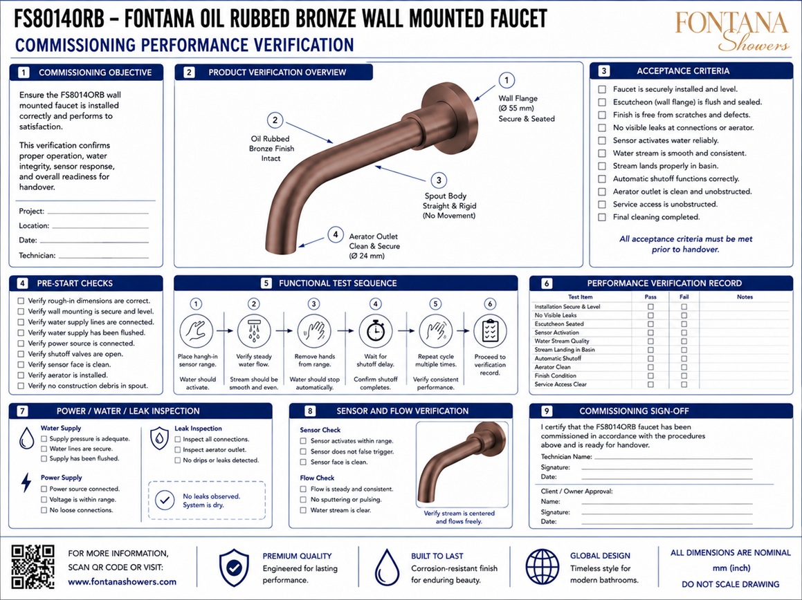
Complete Commissioning Procedure
Shows the complete startup and acceptance sequence for the
FS8014ORB installation. The procedure begins with supply flushing
and connection inspection, continues through controller and sensor
testing, and concludes with flow measurement, shutoff verification,
false-trigger evaluation, leak inspection and recording of final
settings.
Flush Supply Lines
Flush the building supply branch before connecting or operating
the faucet valve kit. Remove construction debris, solder residue,
scale and loose material that could obstruct the inlet strainer,
solenoid diaphragm, flexible hose or vandal-resistant aerator.
Flush until the discharged water is visibly clear.
Open Isolation Valve
Confirm that the local isolation valve is accessible and initially
closed. After flushing and completing the final connections, open
the valve gradually while observing the supply fittings, strainer,
solenoid assembly and flexible hose. Avoid applying a sudden
pressure surge to an untested installation.
Check All Connections
Inspect threaded joints, compression fittings, hose connections,
solenoid ports and the faucet inlet before energizing the control
system. Verify that fittings are aligned, seals are installed,
connectors are fully seated and flexible tubing is free from
kinks, twisting or abrasion.
Energize Controller
Connect the approved transformer, power adapter, battery holder
or battery pack serving the selected valve kit. Confirm the
required voltage, connector orientation and polarity where
applicable. Observe the controller for its normal startup
indication before proceeding with functional testing.
Confirm Sensor Response
Place a hand within the intended activation zone and verify that
the sensor detects the user consistently. Confirm that the
solenoid opens without excessive delay and that water begins
flowing without requiring contact with the faucet or repeated
hand movement.
Verify Water Landing Point
Observe the water stream in relation to the basin centerline,
rear wall, drain, front rim and side edges. The stream should
land within the basin capture area and recommended handwashing
zone without striking the backsplash or passing beyond the usable
bowl area.
Measure Flow Rate
Measure the delivered flow using a calibrated collection vessel
and timer or another approved test method. Compare the result with
the approved product submittal and project requirements. If the
flow is low or irregular, inspect the supply pressure, shutoff
valve, strainer, solenoid valve, hose and aerator.
Confirm Automatic Shutoff
Remove the user’s hands from the sensing area and verify that
water stops automatically. Test the maximum run-time protection
by maintaining continuous activation where permitted by the
installation instructions. Record the final shutoff delay and
maximum run setting.
Check for False Triggering
Observe the faucet with no user present and test nearby reflective
surfaces, lighting, moving objects, water splashes and basin
conditions. The faucet should remain off when the activation
zone is unoccupied. Adjust the sensing range where permitted if
unintended activation occurs.
Inspect for Leaks and Record Settings
Inspect the complete water path during operation and after
automatic shutoff. Document any moisture at the inlet, isolation
valve, strainer, solenoid, hose, faucet connection and outlet.
Record the final sensor range, flow result, shutoff timing, power
configuration and corrective actions.
Engineering note:
Commissioning should be performed using the approved FS8014ORB product
submittal and the instructions supplied with the selected valve kit.
The faucet should not be accepted solely because water flows. Sensor
reliability, shutoff performance, water capture, leakage, flow delivery,
service access and final controller settings should all be verified and
documented.
Recommended Commissioning Sequence
1. Pre-Startup Inspection
Confirm that the faucet, basin, concealed valve kit, service
panel, water supply and electrical components are completely
installed and accessible before startup.
2. Supply Preparation
Flush the branch piping, clean the inlet strainer and verify
that the local isolation valve operates correctly before final
connection to the valve assembly.
3. Hydraulic Inspection
Open the water supply gradually and inspect all concealed and
exposed joints under static pressure before energizing the
controller or activating the faucet.
4. Electrical Startup
Connect the specified power source, confirm controller startup
and verify that sensor, solenoid and power connectors are fully
seated and protected from water exposure.
5. Functional Testing
Test sensor activation, valve opening, water delivery, user
hand-position response and automatic shutoff through repeated
operating cycles.
6. Final Acceptance
Measure flow, confirm the water landing point, inspect for false
triggers and leaks, record final settings and submit the completed
commissioning record.
Performance Verification Criteria
Sensor Reliability
The faucet should activate consistently when hands enter the
intended detection area and remain off when the sensing field
is unoccupied.
Response Time
The controller and solenoid should respond without an excessive
delay that requires users to reposition their hands or repeat
the activation motion.
Water Capture
The stream should land within the usable basin area without
creating avoidable splashback, countertop wetting or overshoot
beyond the basin rim.
Flow Performance
Measured flow should be consistent with the approved product
submittal, available pressure and specified aerator or flow-control
device.
Automatic Shutoff
Water should stop after hands are removed and the maximum
run-time protection should operate in accordance with the
selected controller configuration.
Leak-Free Operation
No visible leakage should be present at supply joints, valve-kit
components, flexible connections, faucet inlet, wall flange or
outlet assembly.
Final Commissioning Record
Project and Fixture Identification
Record the project name, room number, fixture location, product
model, valve-kit model and installation date.
Power Configuration
Record whether the system uses a transformer, power adapter,
battery holder or battery pack and document the measured supply
voltage where required.
Sensor Setting
Record the final sensing range, activation response and any
adjustment completed to prevent false triggering.
Flow and Shutoff Results
Document the measured flow rate, water landing position,
automatic shutoff delay and maximum run-time verification.
Leak Inspection
Record the results of static and operating leak checks and list
any fittings, seals or components that required correction.
Acceptance and Sign-Off
Identify the technician, contractor or commissioning agent who
completed the test and obtain the required project acceptance
signature.
FontanaShowers Installation and Specification Resources
FS8014ORB Product Page
Product description, technical specifications, valve-kit
requirements and available engineering resources for the
FS8014ORB sensor faucet.
FS8014ORB Specification Sheet
Product-specific specification resource for dimensional,
performance and project-submittal verification.
FS8014ORB Installation Instructions
Product-specific installation documentation for assembly,
connections, startup, testing and final adjustment.
Repair and Maintenance Guide
General touchless-faucet troubleshooting, sensor, battery,
solenoid and preventive-maintenance information.
FontanaShowers Installation Hub
Central installation resource for sensor faucets, concealed
valve kits and related commercial restroom fixtures.
Product Warranty Resource
Warranty information relevant to product closeout, maintenance
records and retained project documentation.
Professional Engineering and Commissioning References
Project verification:
Commissioning and performance-verification sheets are procedural
coordination tools and do not replace the approved product submittal or
the instructions supplied with the selected valve kit. The commissioning
agent, plumbing engineer, electrical engineer, contractor, installer and
facility representative should verify supply flushing, valve operation,
connection integrity, controller power, sensor response, water landing,
measured flow, automatic shutoff, false-trigger performance, leak-free
operation, service access and final recorded settings before project
acceptance.
|
|
|