Fontana Wall-Mounted Sensor Faucets™ | Architectural and Engineering Resource
Fontana FS8014ORB Oil Rubbed Bronze Wall-Mounted Automatic Sensor Faucet:
Electrical and Control Diagram
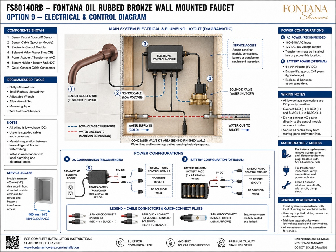
This electrical and control diagram is intended to support architects,
electrical engineers, plumbing engineers, interior designers, contractors,
installers and facility managers coordinating the selected valve-kit
configuration for the Fontana FS8014ORB wall-mounted automatic sensor faucet.
The drawing package identifies the power supply, transformer or battery holder,
electronic controller, infrared sensor, solenoid valve, cable connectors,
applicable polarity, low-voltage cable routing, separation from water lines,
and the service access required for transformer or battery maintenance.

Fontana Oil Rubbed Bronze Wall-Mounted Automatic Sensor Faucet
The Fontana FS8014ORB wall-mounted faucet may be coordinated with a
compatible automatic sensor valve kit using either an AC transformer
or an approved battery-power arrangement. The infrared sensor sends
an activation signal to the electronic control module, which energizes
the solenoid valve and permits water to flow to the faucet. All control
components, connectors and power-service points should remain protected
and accessible.
-
Model:
FS8014ORB
-
Installation:
Wall mounted with concealed sensor controls
-
Finish:
Oil rubbed bronze
-
Fixture type:
Automatic sensor faucet
-
Sensor:
Infrared sensor integrated with faucet trim
-
Controller:
Electronic control module
-
Water control:
Low-voltage solenoid valve
-
AC configuration:
Transformer or approved power adapter
-
DC configuration:
Battery holder or battery pack
-
Connections:
Quick-connect cable connectors
-
Polarity:
Observe positive and negative markings where applicable
-
Service requirement:
Accessible transformer or battery location
Required Electrical and Control Drawing Package
Each diagram should use a consistent line hierarchy, component-numbering
system and product-identification block. Low-voltage control cables should
be visually distinguished from building power wiring and water lines.
The selected AC or battery configuration, connector types, applicable
polarity, sensor route, solenoid connection and service-access requirements
should be clearly identified before concealed walls or access enclosures
are completed.
Complete Electrical and Control Diagram
Shows the full control relationship between the wall-mounted
infrared sensor faucet, sensor cable, electronic controller,
solenoid valve and selected power source. The drawing should
distinguish the low-voltage cable routes from the water path and
identify all accessible connectors, service points and removable
power components.
Power Supply Configuration
Identifies the applicable power arrangement selected for the valve
kit. The drawing should show either the building-powered transformer
configuration or the approved battery-holder configuration and should
label the controlled low-voltage output serving the electronic
module and solenoid assembly.
Transformer or Battery Holder
Documents the transformer, power adapter, battery holder or battery
pack serving the control system. The component should be installed
in a dry, protected and accessible location with sufficient space
for cable connection, inspection, replacement and routine service.
Electronic Controller
Identifies the control module receiving signals from the infrared
sensor and sending the operating command to the solenoid valve.
The drawing should label the sensor, power and valve connections
and show the controller mounted securely within the service-access
area.
Infrared Sensor and Sensor Cable
Shows the infrared sensor incorporated into or connected to the
faucet spout and the low-voltage cable leading to the controller.
The cable route should remain protected from sharp edges, excessive
heat, moisture accumulation, compression and interference from
other building services.
Solenoid Valve Connection
Documents the electrical connection between the controller and
solenoid valve. The solenoid should be shown as the electrically
operated water-control component and should remain accessible for
connection testing, coil inspection, valve service and replacement.
Cable Connectors and Polarity
Identifies the quick-connect plugs or cable connectors used between
the power source, controller, sensor and solenoid valve. Where
polarity applies, positive and negative conductors should be labeled
clearly and connected according to the approved valve-kit
instructions.
Low-Voltage Routing and Water-Line Separation
Shows the low-voltage cable route separately from water piping,
flexible hoses and potential leak points. Cables should be supported
and arranged to avoid direct contact with water lines, fittings,
sharp surfaces and moving service components within the concealed
access area.
Battery or Transformer Service Access
Defines the access required to inspect the transformer, disconnect
the power adapter, replace batteries and service the electronic
controller. The access panel should allow components to be removed
without disturbing permanent tile, wall board or decorative wall
finishes.
Engineering note:
The electrical arrangement should correspond with the specific valve kit
selected for the project. Do not connect building AC power directly to
low-voltage controller, sensor or solenoid terminals. Verify voltage,
connector orientation, polarity, transformer output, battery requirements
and cable routing against the approved FontanaShowers installation
instructions before energizing the system.
Electrical, Plumbing and Service Coordination Considerations
Selected Power Arrangement
Confirm whether the valve kit uses an AC transformer or battery
holder before rough-in so the required power source, access space
and replacement procedure can be coordinated.
Voltage Verification
Verify the required input and output voltage before making
connections. Use only the transformer, adapter, battery holder
and controller specified for the selected valve kit.
Polarity Control
Where connectors are polarity-sensitive, match positive and
negative conductors exactly as identified in the approved wiring
diagram and on the supplied connectors.
Water-Line Separation
Maintain physical separation between low-voltage cables and water
lines, valves and hose connections. Arrange wiring above or away
from likely leak or condensation points where practical.
Connector Protection
Ensure quick-connect plugs are fully seated, locked and protected
from strain. Do not leave loose connectors resting against wet
surfaces or unsupported piping components.
Service Accessibility
Keep the controller, transformer, battery holder, connectors and
solenoid valve accessible for testing, battery replacement,
troubleshooting and future component replacement.
FontanaShowers Installation and Specification Resources
FS8014ORB Product Page
Product information, oil rubbed bronze finish details, technical
specifications and available documentation for the Fontana
FS8014ORB wall-mounted faucet.
FontanaShowers Installation Hub
Central installation information for wall-mounted faucets,
automatic sensor faucets, electrical controls and related
FontanaShowers fixtures.
Commercial Touchless Faucet Collection
Explore related automatic faucet configurations, sensor controls,
power arrangements and concealed operating assemblies for
commercial restroom projects.
Faucet BIM and Coordination Resources
Architectural and engineering resources supporting fixture
selection, controller coordination and multidisciplinary
project documentation.
Electrical and Valve-Kit Installation Resources
General installation information covering transformers,
battery holders, control modules, solenoid valves, cable
connectors, testing and commissioning.
Fontana Bathroom Faucet Collection
View related wall-mounted and sensor-operated bathroom-faucet
options for coordinated commercial and hospitality fixture
selection.
Professional Engineering and Accessibility References
Project verification:
Electrical and control diagrams are coordination tools and do not replace
approved project submittals or the instructions supplied with the selected
valve kit. The architect, electrical engineer, plumbing engineer, contractor
and licensed installer should verify the power supply, transformer or battery
holder, electronic controller, infrared sensor, solenoid valve, connector
types, polarity, low-voltage routing, water-line separation, service access,
electrical protection, accessibility requirements and locally adopted codes
before installation and commissioning.
|
|
|