Fontana Wall-Mounted Sensor Faucets™ | Architectural and Engineering Resource
Fontana FS8014ORB Oil Rubbed Bronze Wall-Mounted Automatic Sensor Faucet:
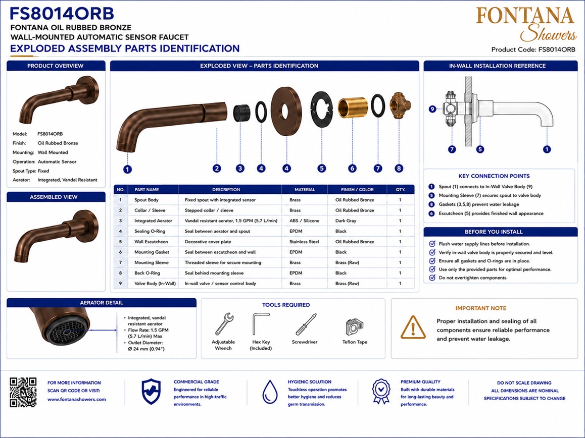
Exploded Assembly and Parts Identification
This exploded-assembly and parts-identification resource is intended to support
architects, plumbing engineers, electrical engineers, contractors, installers,
commissioning personnel and facility managers coordinating the Fontana
FS8014ORB wall-mounted automatic sensor faucet configuration. The drawing
identifies the oil-rubbed-bronze spout, wall flange, mounting sleeve, threaded
inlet body, sensor assembly, sensor cable, aerator, sealing gasket, retaining
hardware, flexible connector, solenoid valve and electronic control module in
their recommended assembly relationship.
Fontana Oil Rubbed Bronze Wall-Mounted Automatic Sensor Faucet
The Fontana FS8014ORB assembly combines the exposed oil-rubbed-bronze
wall-mounted spout with concealed mounting, sensing, water-control and
electronic components. The exploded drawing separates the principal
parts in installation order so the design and construction teams can
verify component identity, orientation, material, connection sequence
and serviceability before installation or replacement work begins.
-
Model:
FS8014ORB
-
Installation:
Wall mounted
-
Finish:
Oil rubbed bronze
-
Primary material:
Brass
-
Fixture configuration:
Automatic sensor faucet
-
Exposed trim:
Spout and wall flange
-
Mounting components:
Sleeve, inlet body and retaining hardware
-
Sensor components:
Sensor assembly and cable
-
Outlet component:
Vandal-resistant aerator
-
Water connection:
Flexible braided connector
-
Water-control component:
Solenoid valve
-
Electronic component:
Control module
Required Exploded Assembly and Parts Drawing Package
Each exploded drawing should use a consistent component-numbering system,
line hierarchy and product-identification block. Components should be
arranged along their assembly axis and connected to a corresponding parts
schedule. The drawing should distinguish exposed trim from concealed
mounting, sensing, plumbing and electronic components. Materials, finishes,
quantities and service relationships should be verified against the approved
product and valve-kit submittals.
Complete Exploded Assembly
Shows the complete FS8014ORB assembly separated into numbered
components, including the oil-rubbed-bronze spout, wall flange,
mounting sleeve, threaded inlet body, sensor assembly, sensor
cable, aerator, gasket, retaining hardware, flexible connector,
solenoid valve and control module. The drawing provides a primary
reference for installation sequencing, servicing and parts
verification.
Oil-Rubbed-Bronze Spout and Wall Flange
Identifies the exposed curved faucet spout and circular wall
flange or escutcheon. Both components should be inspected for
finish damage before installation. The flange should seat evenly
against the finished wall while the spout remains aligned with
the basin centerline and concealed inlet assembly.
Mounting Sleeve and Threaded Inlet Body
Shows the concealed mounting sleeve and threaded brass inlet body
that connect the exposed spout to the wall assembly and water
supply. These parts should be installed in the illustrated order,
secured to the approved backing and aligned perpendicular to the
finished-wall plane.
Sensor Assembly and Sensor Cable
Identifies the infrared sensor assembly and its low-voltage cable
connection to the electronic control system. The cable should be
routed through the designated concealed pathway without sharp
bends, compression, abrasion or contact with unprotected water
connections.
Aerator and Sealing Gasket
Documents the outlet aerator and sealing gasket installed at the
faucet discharge assembly. The aerator conditions the water stream,
while the gasket provides the required seal between assembled
components. Replace damaged, hardened or distorted sealing parts
before final assembly.
Retaining Hardware
Shows the fasteners, washers and related hardware used to secure
the mounting and sensor components. Install only the specified
hardware and tighten it evenly. Excessive torque may damage the
mounting assembly, deform the flange or interfere with sensor and
spout alignment.
Flexible Connector
Identifies the stainless-steel braided flexible connector carrying
water from the controlled outlet to the faucet inlet. The connector
should be routed without twisting, kinking, abrasion or excessive
tension and should remain accessible for inspection and replacement.
Solenoid Valve and Control Module
Shows the concealed solenoid valve and electronic control module
that operate the automatic faucet. The controller receives the
sensor signal and actuates the solenoid valve. Both components
should be mounted securely within an accessible, protected service
area with clearly identified water, sensor and power connections.
Engineering note:
Install components in the sequence shown by the approved exploded
assembly. Confirm that all gaskets, seals, connectors and retaining
components are present before final assembly. Do not substitute hardware,
modify sensor connections or over-tighten threaded parts. Flush water
lines before connecting the solenoid valve and flexible connector, and
disconnect power before installation or service.
Parts Identification and Assembly Considerations
1. Spout and Finish Inspection
Inspect the oil-rubbed-bronze spout and flange for scratches,
dents, coating damage or contamination before installation.
Protect exposed finishes throughout construction.
2. Mounting Sequence
Install the wall flange, mounting sleeve and threaded inlet body
in the documented order. Verify centerline, level and finished-wall
depth before tightening the assembly.
3. Sensor Connection
Route the sensor cable carefully and fully seat the approved
connector at the control module. Do not pull, splice or sharply
bend the supplied cable.
4. Gaskets and Seals
Confirm that every specified gasket and seal is installed in the
correct position. Missing or damaged sealing components can cause
leaks or unstable assembly.
5. Flexible Connection
Support the flexible connector during assembly and ensure that
fittings are properly aligned before tightening. Do not use the
hose to compensate for severely misaligned connections.
6. Controller and Solenoid Access
Mount the control module and solenoid valve where both components
remain accessible for testing, cable inspection, valve service
and future replacement.
Numbered Parts Identification Schedule
Item 1 — Faucet Spout
Oil-rubbed-bronze curved faucet spout manufactured from brass.
Quantity: one.
Item 2 — Wall Flange
Brass wall flange or escutcheon with an oil-rubbed-bronze finish.
Quantity: one.
Items 3 and 4 — Mounting Components
Brass mounting sleeve and threaded inlet body used to support and
connect the wall-mounted faucet. Quantity: one each.
Items 5 and 6 — Sensor Components
Sensor assembly and sensor cable with the specified control-system
connector. Quantity: one each.
Items 7 through 10 — Outlet and Connections
Aerator, sealing gasket, retaining hardware and stainless-steel
braided flexible connector. Verify all quantities and sizes against
the approved parts schedule.
Items 11 and 12 — Operating Components
Solenoid valve and electronic control module serving the automatic
faucet configuration. Quantity: one each, subject to the selected
valve-kit package.
FontanaShowers Installation and Specification Resources
FS8014ORB Product Page
Product information, oil-rubbed-bronze finish details,
technical specifications and available documentation for the
Fontana FS8014ORB wall-mounted faucet.
FontanaShowers Installation Hub
Central installation information for wall-mounted faucets,
automatic sensor faucets, concealed valve kits and related
FontanaShowers fixtures.
FS8014ORB Parts Verification
Review current product documentation before ordering replacement
spout, sensor, mounting, aerator, connector or control components.
Assembly and Installation Guidance
General guidance covering component identification, mounting,
connections, cable routing, sealing, testing and final assembly.
Replacement-Part Compatibility
Confirm model, finish, dimensions, connector type, voltage and
valve-kit compatibility before ordering or installing replacement
components.
Testing and Commissioning Resources
General resources covering supply flushing, leak testing, sensor
verification, solenoid operation and final faucet commissioning.
Professional Engineering and Performance References
Project verification:
Exploded-assembly and parts-identification drawings are coordination and
maintenance tools and do not replace approved product or valve-kit
submittals. The architect, plumbing engineer, electrical engineer,
contractor, installer and facility maintenance team should verify the
spout, wall flange, mounting sleeve, threaded inlet body, sensor assembly,
sensor cable, aerator, sealing gasket, retaining hardware, flexible
connector, solenoid valve, control module, materials, finishes, quantities,
connection sizes, voltage and replacement-part compatibility before
installation or service.
|
|
|