Fontana Wall-Mounted Sensor Faucets™ | Architectural and Engineering Resource
Fontana FS8014ORB Oil Rubbed Bronze Wall-Mounted Faucet:
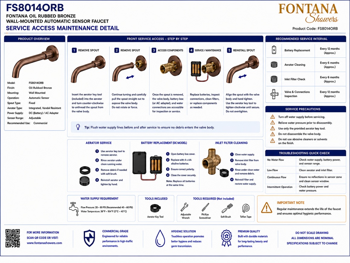
Service Access and Maintenance Detail
This service-access and maintenance-detail resource is intended to support
architects, plumbing engineers, electrical engineers, contractors, installers,
commissioning personnel and facility managers coordinating the Fontana
FS8014ORB wall-mounted faucet with a compatible concealed sensor valve kit.
The drawing package identifies the recommended access-panel location,
solenoid-removal direction, strainer-removal direction, controller access,
power-source access, flexible-hose replacement route, cable-disconnection
points, aerator service procedure, minimum working clearances and components
that must not be permanently concealed.
Fontana Oil Rubbed Bronze Wall-Mounted Faucet
The Fontana FS8014ORB is a solid-brass wall-mounted faucet with an
oil rubbed bronze finish. When coordinated with a compatible automatic
sensor valve kit, the installation includes concealed water-control,
electronic and power components that require permanent maintenance
access. The service layout should permit inspection, cleaning,
disconnection and replacement without removing tile, stone, wall board
or other permanent architectural finishes.
-
Model:
FS8014ORB
-
Installation:
Wall mounted
-
Finish:
Oil rubbed bronze
-
Primary material:
Solid brass
-
System configuration:
Faucet with compatible concealed sensor valve kit
-
Water-control component:
Solenoid valve
-
Filtration component:
Accessible inlet strainer
-
Electronic component:
Control module
-
Power options:
Transformer or battery holder, as selected
-
Water connection:
Flexible supply hose
-
Outlet service:
Removable aerator
-
Access requirement:
Removable service panel required
Required Service Access and Maintenance Drawing Package
Each service drawing should use a consistent scale, component-numbering
system, directional-arrow convention and product-identification block.
The access panel should be shown relative to the finished wall, valve-kit
components and working-clearance envelope. Removal paths for the solenoid,
strainer, flexible hose, controller, power source and cable connectors
should remain unobstructed. Components requiring routine inspection,
cleaning, adjustment or replacement should never be permanently enclosed.
Complete Service Access Detail
Shows the complete maintenance relationship between the removable
access panel, concealed solenoid valve, strainer, controller,
transformer or battery holder, flexible water connection, cable
connectors and wall-mounted faucet. Directional arrows should
identify how each component is removed and the clear working area
required in front of the assembly.
Recommended Access-Panel Location
Identifies the preferred removable access-panel location adjacent
to or directly in front of the concealed valve-kit assembly. The
panel should provide direct reach to the shutoff valve, strainer,
solenoid, controller, power source, flexible hose and cable
connectors without interference from framing or fixed equipment.
Solenoid-Removal Direction
Shows the direction in which the solenoid valve body, coil or
complete valve assembly must move for removal. The service cavity
should provide sufficient clearance to disconnect the electrical
lead and plumbing connections before the component is withdrawn
through the access opening.
Strainer-Removal Direction
Documents the direction required to remove the strainer cap,
screen or complete Y-strainer assembly. Maintain clear space around
the service end so maintenance personnel can isolate the water,
remove accumulated debris and reinstall the screen without
dismantling unrelated components.
Controller and Cable Access
Identifies the electronic controller and its sensor, solenoid and
power connectors. The drawing should show sufficient hand clearance
to release quick-connect plugs, inspect terminals and remove the
controller from its mounting position without pulling or damaging
the associated cables.
Power-Source Access
Shows the service position for the transformer, power adapter,
battery holder or approved battery pack. Power components should
remain dry, ventilated where required and accessible for inspection,
disconnection, battery replacement and complete component removal.
Flexible-Hose Replacement
Illustrates the disconnection and withdrawal path for the flexible
supply hose. The service opening should permit access to both hose
fittings and provide enough space to remove the hose without
sharp bending, twisting or cutting adjacent wiring and plumbing
components.
Aerator Service
Identifies the faucet outlet and the required clearance for
aerator removal, cleaning and replacement. The designated aerator
tool should engage the outlet from below without interference from
the basin rim, countertop or backsplash. Protect the oil rubbed
bronze finish during all service work.
Minimum Working Clearances
Defines the clear working zone required in front of and around the
service panel. The clearance should allow the panel to open or be
removed completely and should provide adequate reach for tools,
component withdrawal, electrical disconnection and water-control
maintenance.
Components Not to Be Permanently Concealed
Identifies the shutoff valve, strainer, solenoid valve, controller,
power source, cable connectors, flexible-hose fittings and other
serviceable joints that must remain reachable. These components
should not be buried behind permanent tile, masonry, stone or
nonremovable wall construction.
Engineering note:
Service access should be established before the wall is closed and before
architectural finishes are installed. Confirm that each serviceable
component can be disconnected and removed through the proposed access
opening. An access panel that exposes a component but does not permit its
removal is not adequate for long-term maintenance.
Service Access and Maintenance Coordination Considerations
Panel Size and Orientation
Size and orient the access panel around the actual component
layout rather than using a generic opening that may not permit
valve, controller or power-source removal.
Water Isolation
Keep the local shutoff valve visible and operable through the
service opening so water can be isolated before strainer,
solenoid or hose maintenance begins.
Electrical Disconnection
Provide enough room to disconnect power, sensor and solenoid
cables without pulling on conductors or removing unrelated
plumbing components.
Component Withdrawal Paths
Keep framing, pipes, brackets and cables outside the required
removal path for the solenoid valve, strainer, controller,
transformer and flexible hose.
Moisture Protection
Arrange electronic and power components above or away from likely
leak points and provide a service layout that permits inspection
for moisture or condensation.
Finish Coordination
Coordinate the panel frame, door and surrounding finish so the
opening remains discreet but clearly identifiable and removable
by maintenance personnel.
Recommended Maintenance Procedures
1. Isolate Water and Power
Close the local shutoff valve and disconnect the transformer or
battery source before servicing concealed plumbing or electronic
components.
2. Inspect Access Area
Check the service cavity for leaks, condensation, corrosion,
loose wiring, damaged hoses and obstructed component-removal paths.
3. Clean the Strainer
Remove the strainer screen in the indicated direction, rinse
away debris and reinstall the screen and cap with the specified
seals in place.
4. Test Solenoid Operation
Inspect the solenoid connections and test opening and closing
operation. Replace the valve or coil where cleaning and electrical
testing do not restore dependable performance.
5. Inspect Cables and Hose
Check quick-connect plugs, cable insulation and flexible-hose
braiding for wear, water exposure, kinks or abrasion. Replace
damaged components with approved parts.
6. Service the Aerator
Use the designated aerator tool to remove and clean the outlet
insert. Reinstall it securely and verify a uniform stream after
water and power are restored.
Components Requiring Permanent Access
Shutoff Valve and Strainer
Must remain accessible for water isolation, debris removal and
routine preventive maintenance.
Solenoid Valve
Must remain accessible for electrical testing, valve cleaning,
coil service and complete replacement.
Control Module
Must remain accessible for connector inspection, programming
where applicable, troubleshooting and replacement.
Transformer or Battery Holder
Must remain accessible for disconnection, inspection, battery
replacement and power-component service.
Flexible-Hose Connections
Must remain accessible for leak inspection, fitting tightening
and complete hose replacement.
Cable Connectors
Must remain accessible for disconnection, polarity verification,
troubleshooting and replacement of sensor or control components.
FontanaShowers Installation and Specification Resources
FS8014ORB Product Page
Product information, oil rubbed bronze finish details,
technical specifications and available documentation for the
Fontana FS8014ORB wall-mounted faucet.
FontanaShowers Installation Hub
Central installation and service information for wall-mounted
faucets, automatic sensor controls and concealed valve kits.
FS8014ORB Service Verification
Review current product documentation before establishing access
panels or ordering replacement faucet and valve-kit components.
Valve-Kit Maintenance Guidance
General guidance covering shutoff valves, strainers, solenoid
valves, control modules, power sources, hoses and cable connectors.
Replacement-Part Compatibility
Confirm model, connection size, voltage, connector type, finish
and valve-kit compatibility before ordering replacement parts.
Testing and Commissioning Resources
General information covering supply flushing, leak testing,
sensor verification, solenoid operation and final commissioning.
Professional Engineering and Maintenance References
Project verification:
Service-access and maintenance drawings are coordination tools and do not
replace approved product or valve-kit documentation. The architect, plumbing
engineer, electrical engineer, contractor, installer and facility maintenance
team should verify the access-panel location, working clearances, solenoid
and strainer removal paths, controller and power access, flexible-hose
replacement route, cable-disconnection points, aerator service clearance,
water isolation, electrical safety and all components that must remain
accessible before the wall assembly is closed.
|
|
|