Fontana Wall-Mounted Faucets™ | Architectural and Engineering Resource
Fontana FS8014ORB Oil Rubbed Bronze Wall-Mounted Faucet:
Aerator and Outlet Detail
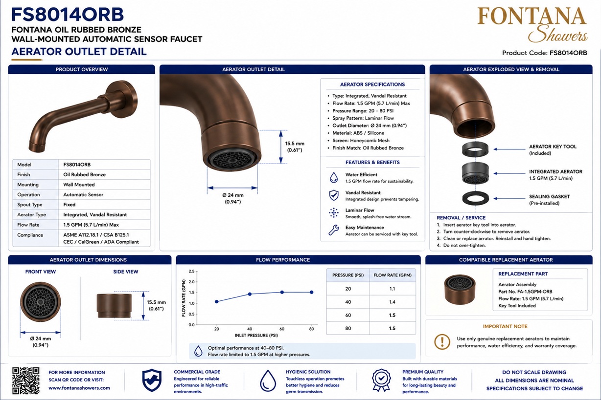
This aerator and outlet-detail resource is intended to support architects,
plumbing engineers, contractors, installers, commissioning personnel and
facility managers coordinating the outlet assembly of the Fontana FS8014ORB
oil rubbed bronze wall-mounted faucet. The enlarged technical drawing identifies
the vandal-resistant aerator, outlet housing, aerator insert, retaining feature,
thread size, outlet diameter, removal tool, flow direction, cleaning procedure
and recommended replacement sequence.
Fontana Oil Rubbed Bronze Wall-Mounted Faucet
The Fontana FS8014ORB is a solid-brass wall-mounted faucet with an
oil rubbed bronze finish and a serviceable outlet assembly. The
vandal-resistant aerator is retained within the outlet housing and
requires the designated removal tool for safe extraction, cleaning
and replacement. Routine aerator maintenance helps preserve the
intended stream pattern, flow performance and outlet appearance.
-
Model:
FS8014ORB
-
Installation:
Wall mounted
-
Finish:
Oil rubbed bronze
-
Faucet material:
Solid brass
-
Aerator type:
Vandal-resistant laminar-flow aerator
-
Aerator material:
316 stainless steel, as illustrated
-
Thread size:
M24 × 1.0
-
Outlet diameter:
Ø24 mm (0.94 inch)
-
Outlet depth:
Approximately 12 mm (0.47 inch)
-
Nominal flow rate:
0.5 GPM (1.9 L/min) at 60 PSI, as illustrated
-
Stream type:
Laminar
-
Service method:
Special aerator-removal tool
Required Aerator and Outlet Detail Drawing Package
Each outlet-detail drawing should use a consistent scale, component-numbering
system, dimension style and product-identification block. The enlarged view
should distinguish the faucet outlet housing from the removable aerator
insert and retaining components. Thread designation, outlet diameter,
assembly sequence, removal-tool engagement and water-flow direction should
be shown clearly so the aerator can be inspected and serviced without
damaging the faucet finish or outlet housing.
Complete Aerator and Outlet Detail
Shows the enlarged faucet outlet assembly with the housing,
aerator insert, internal retaining feature and finish-matched
vandal-resistant aerator separated in an exploded arrangement.
The drawing also identifies the thread size, outlet diameter,
water-flow direction, removal tool and servicing sequence.
Outlet Housing
Identifies the machined outlet housing formed at the end of the
curved faucet spout. The housing contains the internal thread and
retention surfaces used to support the aerator assembly. Inspect
the housing for damaged threads, mineral deposits or foreign
material before reinstalling the aerator.
Vandal-Resistant Aerator
Documents the finish-matched, vandal-resistant aerator installed
at the faucet outlet. Its concealed engagement features discourage
removal with common tools while allowing authorized maintenance
personnel to remove it using the designated service tool.
Aerator Insert
Shows the internal laminar-flow insert that conditions the water
stream before discharge. The insert should remain clean and
undamaged so water exits in a controlled pattern without excessive
spray, stream distortion or uneven flow.
Retaining Feature
Identifies the internal retaining ring, hex retainer or comparable
feature that secures the aerator insert within the outlet housing.
The retaining component should be installed in the illustrated
order and should not be modified, omitted or replaced with an
unapproved part.
Thread Size and Outlet Diameter
Documents the principal connection and outlet dimensions required
for maintenance and replacement-part verification. The illustrated
outlet assembly uses an M24 × 1.0 thread and a nominal outlet
diameter of 24 mm, equivalent to approximately 0.94 inch.
Removal Tool and Flow Direction
Shows the special removal tool engaging the concealed aerator
slots and identifies the downward direction of water flow through
the completed outlet assembly. Do not use pliers, adjustable
wrenches or other tools that could deform the aerator or damage
the oil rubbed bronze finish.
Cleaning and Replacement Procedure
Provides the recommended sequence for removing, cleaning,
inspecting and reinstalling the aerator assembly. The detail
should identify the direction of rotation, hand-tightening
requirement and final use of the service tool to secure the
aerator without excessive torque.
Engineering note:
Use only the designated aerator-removal tool and approved replacement
components. Do not grip the outlet housing or finish with pliers or
wrenches. Excessive tightening may damage the aerator, retaining feature,
internal threads or faucet finish. Verify the replacement aerator, thread
size and flow rating against the approved FontanaShowers product
documentation before installation.
Aerator Removal, Cleaning and Replacement Sequence
1. Isolate and Protect
Shut off the water supply where required and protect the faucet,
basin and surrounding finishes before beginning aerator service.
2. Engage Removal Tool
Insert the designated removal tool fully into the aerator slots
and confirm that it engages securely before applying rotational
force.
3. Remove Aerator
Turn the tool counterclockwise while supporting the outlet
housing. Remove the aerator, retaining component and insert in
the documented sequence.
4. Clean Components
Rinse removable components with clean warm water and remove
debris using a soft brush. Avoid abrasive pads, metal tools and
harsh chemicals.
5. Inspect and Replace
Check the insert, retaining feature, threads and seals for wear,
distortion or mineral accumulation. Replace damaged components
with approved parts.
6. Reassemble and Test
Reinstall the parts in the correct order, tighten by hand and
use the service tool only to secure the aerator. Restore water
and verify the stream pattern and leak-free operation.
Outlet Performance and Maintenance Considerations
Stream Pattern
Confirm that the cleaned or replaced aerator produces a stable,
uniform laminar stream without side spray, pulsing or irregular
discharge.
Flow Performance
Investigate reduced flow by checking the aerator insert, inlet
strainer, supply pressure, solenoid valve and flexible supply
connection.
Mineral Accumulation
Establish a cleaning frequency appropriate for local water
quality and fixture usage. Hard-water conditions may require
more frequent aerator inspection.
Finish Protection
Avoid abrasive cleaners and metal tools on the oil rubbed bronze
surface. Clean visible faucet surfaces with a soft damp cloth and
dry them after service.
Replacement Interval
Inspect the aerator during preventive maintenance and replace it
when cleaning no longer restores the required stream pattern or
flow performance.
Service Documentation
Record cleaning dates, replacement parts and recurring outlet
issues so facility personnel can identify water-quality or
systemic maintenance conditions.
FontanaShowers Installation and Specification Resources
FS8014ORB Product Page
Product information, oil rubbed bronze finish details,
technical specifications and available documentation for the
Fontana FS8014ORB wall-mounted faucet.
FontanaShowers Installation Hub
Central installation and maintenance information for
wall-mounted faucets, automatic faucets and related
FontanaShowers fixtures.
FS8014ORB Outlet Specifications
Review the current faucet specifications and available technical
documentation before ordering replacement aerators or outlet
components.
Aerator Maintenance Guidance
General guidance covering faucet outlet inspection, aerator
removal, cleaning, replacement, stream testing and finish care.
Replacement-Part Verification
Confirm the current thread size, outlet diameter, flow rating,
finish and replacement-component compatibility before ordering
service parts.
Fixture Testing and Commissioning
General resources covering supply flushing, outlet testing,
leak inspection, water-stream verification and final fixture
commissioning.
Professional Engineering and Performance References
Project verification:
Aerator and outlet-detail drawings are coordination and maintenance tools
and do not replace approved product documentation. The architect, plumbing
engineer, contractor, installer and facility maintenance team should verify
the vandal-resistant aerator, outlet housing, insert, retaining feature,
thread size, outlet diameter, removal tool, flow rating, cleaning method,
replacement sequence, finish compatibility and approved service parts before
performing maintenance or modifying the faucet assembly.
|
|
|