Fontana Wall-Mounted Sensor Faucets™ | Architectural and Engineering Resource
Fontana FS8014ORB Oil Rubbed Bronze Wall-Mounted Automatic Sensor Faucet:
Sensor Detection Zone
This sensor-detection-zone resource is intended to support architects,
plumbing engineers, electrical engineers, interior designers, contractors,
installers and facility managers coordinating the functional operation of
the Fontana FS8014ORB wall-mounted automatic sensor faucet. The drawing
package identifies the sensor position, infrared beam direction, detection
envelope, recommended hand-activation zone, minimum and maximum sensing
distances, basin rim, reflective-surface interference zone and conditions
that could cause unintended or false activation.
Fontana Oil Rubbed Bronze Wall-Mounted Automatic Sensor Faucet
The Fontana FS8014ORB wall-mounted faucet can be coordinated as part
of an automatic sensor-faucet installation with the sensor positioned
at the spout outlet. The infrared detection field extends downward
toward the intended handwashing area above the basin. Correct spout
alignment, mounting height, basin position and control-module
adjustment are required for consistent hands-free activation.
-
Model:
FS8014ORB
-
Installation:
Wall mounted
-
Finish:
Oil rubbed bronze
-
Material:
Solid brass
-
Fixture type:
Automatic sensor faucet
-
Sensor position:
At the spout outlet
-
Detection direction:
Downward infrared beam
-
Minimum sensing distance:
60 mm (2-3/8")
-
Recommended activation zone:
100–150 mm (4–6")
-
Maximum sensing distance:
200 mm (7-7/8")
-
Spout projection:
108 mm (7"), as shown
-
Application:
Commercial and institutional restrooms
Required Sensor Detection Zone Drawing Package
Each drawing should use a consistent scale, line hierarchy and product
identification block. The functional elevation should reference the
faucet centerline, basin centerline, finished-wall plane, basin rim and
sensor location. The detection field should be represented separately
from physical fixture dimensions so designers and installers can clearly
evaluate the intended hand-activation area and nearby interference risks.
Standard Sensor Detection Zone
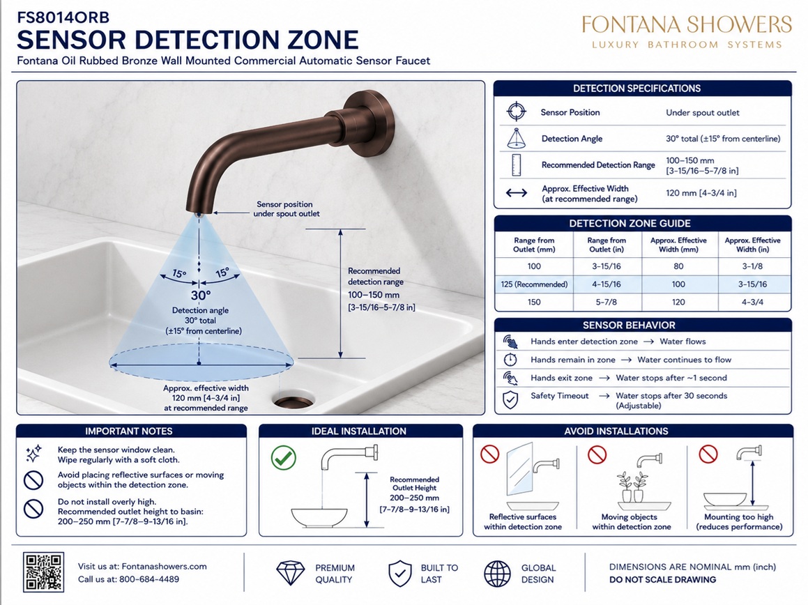
Shows the complete functional relationship between the
wall-mounted sensor faucet, infrared beam, detection envelope,
recommended hand position, basin rim and reflective-surface
interference area. The drawing provides the primary reference
for coordinating faucet placement, sensing distance and basin
alignment before installation and commissioning.
Sensor Position
Identifies the infrared sensor at or near the forward outlet
of the faucet spout. The sensor should face the intended
handwashing area without being obstructed by the outlet,
basin rim, backsplash, accessories or decorative elements.
Infrared Beam Direction
Illustrates the direction of the infrared beam extending
downward from the sensor toward the user’s hands. The beam
should be aligned with the basin centerline and should not
intersect surrounding walls, countertop edges or reflective
objects before reaching the intended activation area.
Detection Envelope
Defines the approximate three-dimensional sensing field beneath
the spout. The envelope is shown as a widening zone rather than
a single line because activation can occur within a range of
positions depending on sensor adjustment, hand angle, surface
reflectivity and ambient conditions.
Recommended Hand-Activation Zone
Identifies the preferred area in which the user should place
their hands for consistent activation. The drawing indicates a
recommended hand-activation zone approximately 100–150 mm
(4–6 inches) below the sensor, subject to final commissioning
and adjustment.
Minimum and Maximum Sensing Distance
Shows the functional limits of the detection field. The minimum
sensing distance is approximately 60 mm (2-3/8 inches), while
the maximum sensing distance is approximately 200 mm
(7-7/8 inches). Final operating distance should be field-verified
after installation.
Basin Rim and Centerline
Documents the relationship between the detection field, basin rim,
faucet centerline and basin centerline. The basin should be centered
below the faucet, and the rim should remain outside the active
sensing zone to prevent continuous or unintended operation.
Reflective-Surface and False-Activation Zones
Identifies nearby surfaces or conditions that could reflect the
infrared signal back toward the sensor. Mirrors, polished metal,
glossy tile, moving objects, direct lighting, water splashes and
steam may interfere with detection or cause unintended activation
if located within the sensing field.
Engineering note:
The illustrated sensing distances and detection envelope are functional
references and should be verified during field commissioning. Final sensor
performance may be affected by control-module settings, wall finish,
basin material, lighting, nearby reflective surfaces, water movement and
environmental conditions. Adjust and test the sensor in accordance with
the approved FontanaShowers installation instructions before the fixture
is placed into service.
Architectural, Plumbing and Sensor Coordination Considerations
Faucet and Basin Alignment
Align the faucet centerline with the basin centerline so the
detection field and water stream remain within the usable
handwashing area.
Basin-Rim Clearance
Maintain sufficient vertical clearance between the sensor and
basin rim so the basin does not enter the active detection
envelope or cause continuous operation.
Reflective Materials
Evaluate mirrors, polished stone, stainless steel, glossy tile
and reflective basin surfaces that could redirect infrared
energy toward the sensor.
Lighting Conditions
Avoid positioning strong spotlights, direct sunlight or high-
intensity lighting so that it points directly toward the sensor
or crosses the sensing field.
Water and Steam Interference
Keep the sensor clear of water splashes, heavy condensation,
steam and cleaning spray that could interrupt detection or cause
temporary false activation.
Field Commissioning
Test minimum, recommended and maximum hand positions after all
finishes, mirrors, accessories and lighting are installed, and
adjust the sensing range where permitted.
FontanaShowers Installation and Specification Resources
Professional Engineering and Accessibility References
Project verification:
Sensor-detection-zone drawings are functional coordination tools and do
not replace approved project submittals. The architect, plumbing engineer,
electrical engineer, contractor and licensed installer should verify the
sensor position, infrared beam direction, detection envelope, activation
range, basin-rim clearance, faucet and basin centerlines, reflective
surfaces, lighting conditions, concealed control components, accessibility
criteria and locally adopted codes before installation and commissioning.
|
|
|