Fontana Large Rain Shower Systems™ | Architectural and Engineering Resource
Fontana Large Rain Shower Head System:
Body-Jet & Hand-Shower Placement Guide
This fixture-placement resource is intended to support architects, plumbing
engineers, interior designers, contractors, installers and facility managers
coordinating the Fontana large rain shower system within residential,
hospitality and commercial shower environments. The drawing package communicates
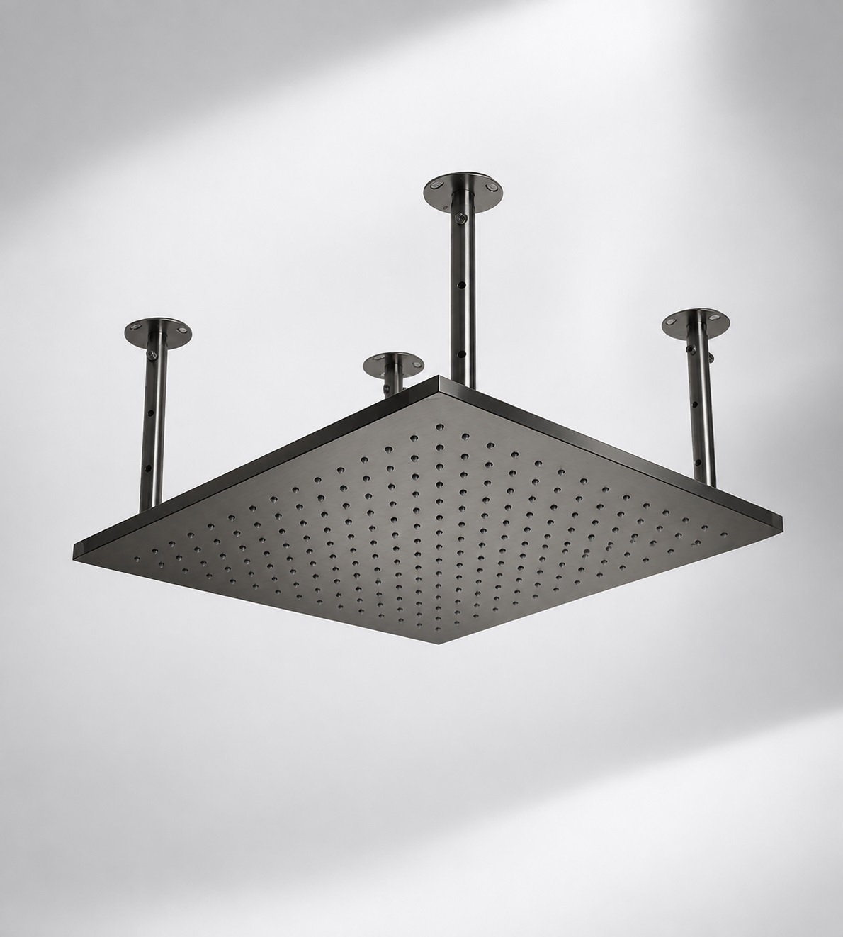
the 600 mm square rain shower head, four wall-mounted body jets, hand shower,
slide bar, hose outlet, thermostatic control valve, recommended mounting heights,
body-jet spacing, spray angles, user standing zone, reach ranges and important
enclosure clearances.
Fontana Large Rain Shower System with Body Jets and Hand Shower
The system combines a 600 mm square overhead rain shower head, four
wall-mounted body jets, a hand shower on an adjustable slide bar,
thermostatic control valve and wall-mounted hose outlet. The placement
guide is intended to help coordinate the primary standing position,
body-spray coverage and hand-shower reach while keeping all active spray
within the waterproof shower enclosure.
- Rain shower head: 600 mm (23.62 in.) square
- Rain shower outlet height: 2100 mm (82.68 in.) AFF
- Typical ceiling height: 2400 mm (94.49 in.)
- Upper body-jet centerline: 1200 mm (47.24 in.) AFF
- Lower body-jet centerline: 950 mm (37.40 in.) AFF
- Body-jet spacing: Approximately 450 mm (17.72 in.) center-to-center
- Typical body-jet row spacing: Approximately 250 mm (9.84 in.)
- Control valve height: 1050 mm (41.34 in.) AFF
- Hose outlet height: 850 mm (33.46 in.) AFF
- Hand-shower slide bar: Approximately 700 mm (27.56 in.) long
- Hand-shower adjustment zone: Approximately 1100–1800 mm (43.31–70.87 in.) AFF
Required Body-Jet and Hand-Shower Placement Drawing Package
Each placement drawing should use a consistent finished-floor datum, centerline
system and dimension style. The package should clearly identify rain-head
centerline and elevation, upper and lower body-jet rows, horizontal and
vertical jet spacing, spray direction, user standing zone, hand-shower
reach, slide-bar limits, hose-outlet position, control-valve location and
clearance from enclosure corners, door swings and trim.
Body-Jet & Hand-Shower Placement Guide
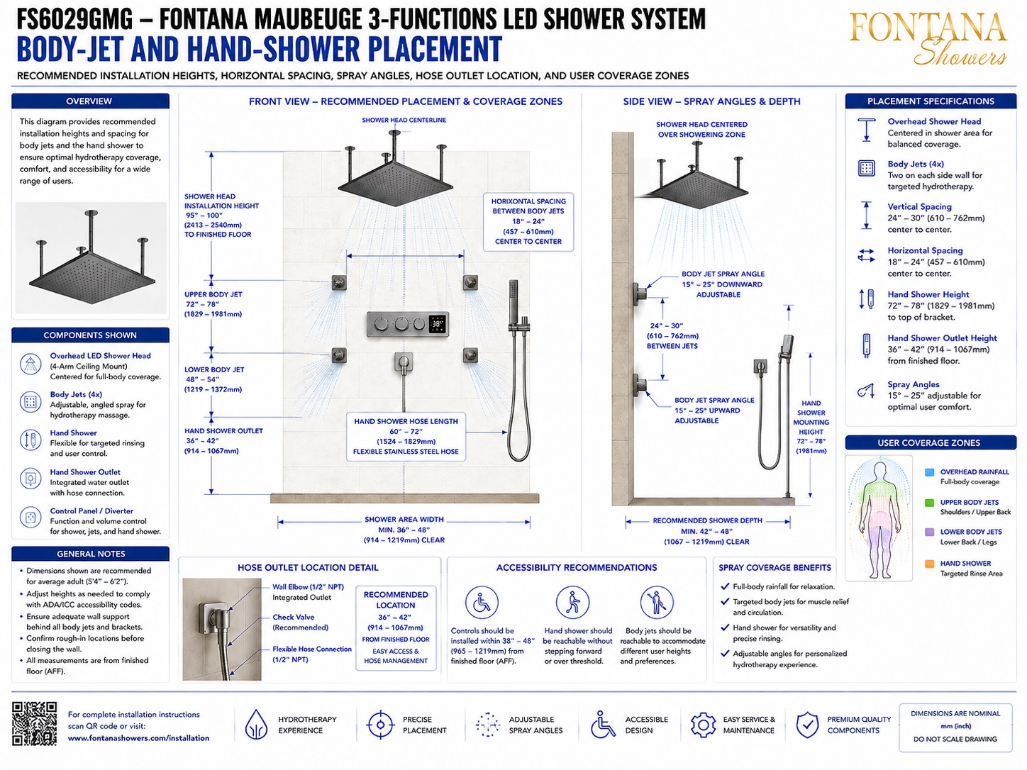
Shows the complete recommended arrangement for the 600 mm rain shower head, four wall-mounted body jets, hand shower, slide bar, hose outlet and thermostatic control. This drawing provides the primary reference for rough-in heights, user reach, spray coverage and enclosure coordination.
Front Elevation
Establishes the principal installation heights above finished floor, including the rain-shower outlet at 2100 mm, upper body-jet row at 1200 mm, lower body-jet row at 950 mm, control valve at 1050 mm and hose outlet at 850 mm.
Body-Jet Horizontal Spacing
Shows the four body jets arranged symmetrically about the user centerline. The drawing indicates approximately 450 mm center-to-center spacing across each row, with each jet located about 225 mm from the main centerline.
Body-Jet Vertical Spacing
Coordinates the upper and lower body-jet rows with a typical vertical separation of approximately 250 mm. The two-height arrangement is intended to provide balanced torso and lower-body spray coverage.
Body-Jet Spray Angles
Defines typical spray-direction guidance. Upper jets are shown aimed approximately 0–10° downward, while lower jets are shown approximately 10–15° upward so the spray patterns converge toward the user's torso and body zone rather than the face.
User Standing & Spray Reach
Illustrates a recommended standing distance of approximately 450–600 mm from the wall and a typical horizontal body-jet spray reach of approximately 500–700 mm. These references help keep the active spray envelope within the waterproof enclosure.
Rain-Shower Alignment
Shows the 600 mm square rain head centered over the primary standing position, with a typical outlet elevation of 2100 mm above finished floor. The ceiling arm or drop should be coordinated with the actual ceiling height and specified shower-head position.
Hand-Shower Reach & Slide Bar
Illustrates a 700 mm slide bar with a hand-shower holder adjustment range of approximately 1100–1800 mm above finished floor. The overall reachable hand-shower zone is shown extending approximately 900–1800 mm AFF.
Control, Hose Outlet & Clearances
Coordinates the thermostatic valve, hose outlet, hand-shower hose path and adjacent enclosure elements. The drawing recommends keeping body jets clear of corners and trim, including a nominal minimum of 150 mm from a body-jet centerline to an adjacent corner.
Engineering note:
The installation heights and spacing shown are nominal placement guidelines.
Final fixture elevations, body-jet spacing, spray angles, hand-shower reach
and control locations should be coordinated with actual users, enclosure
dimensions, finished surfaces, waterproofing, concealed plumbing and the
approved project submittal before rough-in.
Architectural and Plumbing Coordination Considerations
Finished-Floor Reference
Set all vertical fixture dimensions from the final finished-floor elevation, including tile, mortar bed, shower pan and other floor build-up.
Common Centerlines
Align the upper and lower body jets on consistent vertical centerlines so the four-jet array reads symmetrically and produces balanced spray coverage.
Spray Containment
Verify body-jet and hand-shower spray trajectories remain inside the waterproof enclosure and do not overshoot glass doors, openings or adjacent dry areas.
User Reach
Place the control valve, hand shower and slide bar within comfortable reach from the primary standing zone without forcing the user into direct spray.
Enclosure Clearance
Keep body jets, slide-bar hardware and the hand-shower hose clear of door swings, hinges, handles, enclosure trim and corner conditions.
Rough-In Verification
Confirm concealed piping, backing, valve depth and fixture centerlines before wall finishes are installed to avoid field relocation after waterproofing.
FontanaShowers Installation and Specification Resources
Professional Engineering and Accessibility References
Project verification:
Body-jet and hand-shower placement drawings are coordination tools and do not
replace approved project submittals. The architect, plumbing engineer,
contractor and licensed installer should verify fixture elevations, body-jet
spacing, spray trajectories, user standing zone, hand-shower reach, control
and hose-outlet locations, wall framing, waterproofing, service access,
enclosure clearances, accessibility criteria and locally adopted plumbing
codes before installation.
|
|
|