Fontana Large Rain Shower Systems™ | Architectural and Engineering Resource
Fontana Large Rain Shower Head & Rain Shower System:
Service Access & Maintenance Detail Guide
This service-access and maintenance resource is intended to support architects,
plumbing engineers, facility managers, contractors, installers and maintenance
personnel coordinating a Fontana large rain shower system for long-term
serviceability. The drawing package communicates access-panel location,
rain-shower-head removal, hand-shower and body-jet servicing, valve and filter
access, optional electrical access, working clearances, recommended tools and
a typical preventive-maintenance schedule.
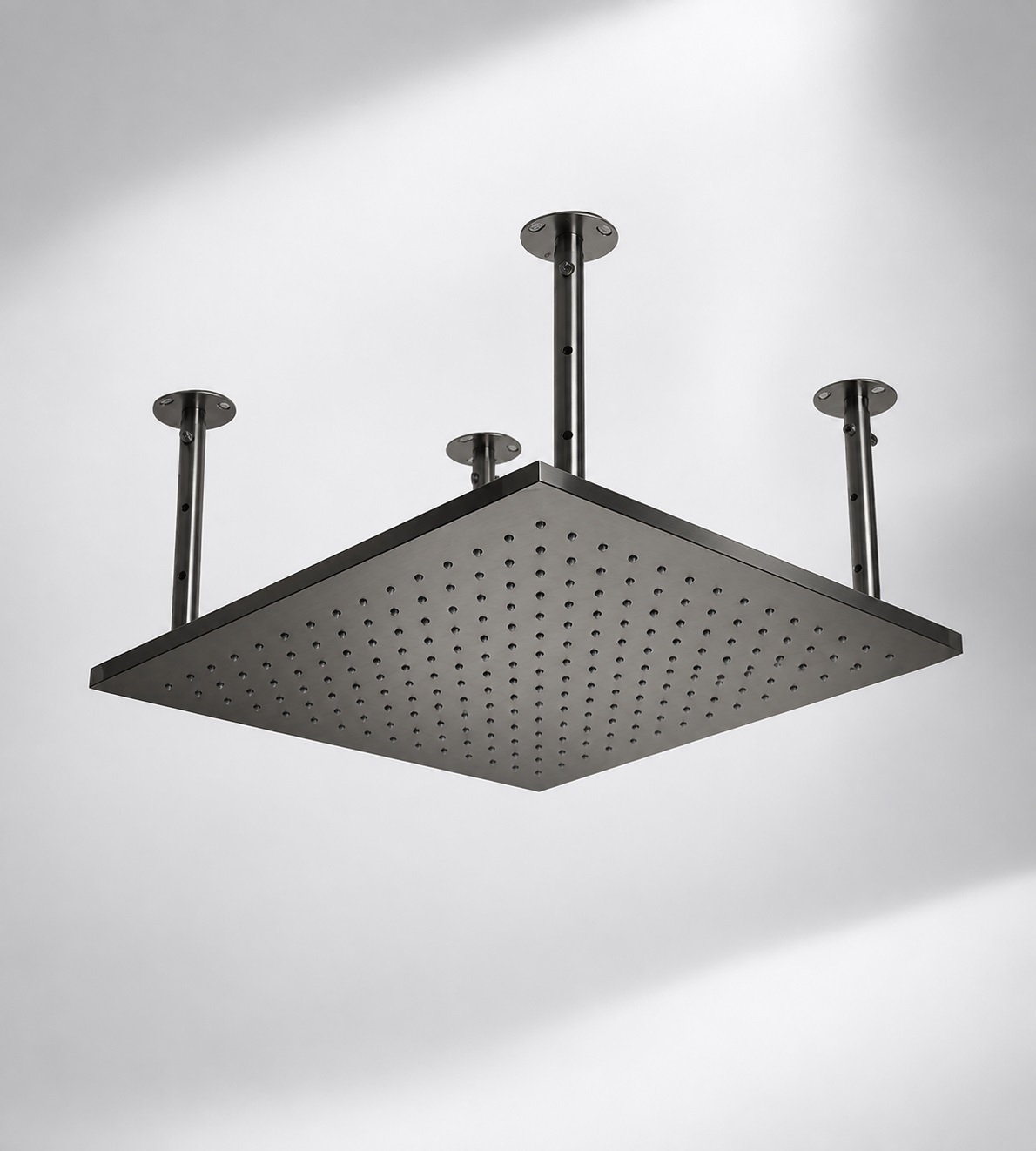
Fontana Large Rain Shower System — Serviceable Installation
The system is organized so the principal components can be inspected,
cleaned and maintained without removing permanent construction. Dedicated
access should be provided for the rain head, hand shower, body jets,
thermostatic or pressure-balance valve, diverter controls, filters,
check valves, supply connections and, where applicable, LED controls and
transformer equipment.
- Typical access-panel width: Approximately 500–600 mm (19-11/16–23-5/8 in.)
- Minimum lower service clearance: Approximately 300 mm (11-3/4 in.)
- Illustrated service-zone height: Approximately 1200 mm (47-1/4 in.) maximum
- Working side clearance: Approximately 600 mm (23-5/8 in.) minimum
- Vertical service reference: Approximately 2100 mm (82-11/16 in.) to floor
- Access panel: Waterproof, corrosion-resistant and removable
- Valve access: Thermostatic / pressure-balance and diverter components
- Filter access: Check valves, strainers and serviceable filters
- Electrical access: LED controller / transformer where applicable
- Rain-head maintenance: Removal, descaling and nozzle cleaning
- Service documentation: Record final access locations on as-built drawings
Required Service Access and Maintenance Drawing Package
Each service drawing should use a consistent component-numbering system,
finished-floor datum and access-zone notation. The package should clearly
identify the main access panel, rain-head removal direction, hand-shower
and body-jet service points, valve and filter locations, optional electrical
equipment, minimum working clearances and recommended maintenance intervals.
Service paths should remain unobstructed after wall, ceiling, glass and
accessory installation.
Service Access & Maintenance Detail Guide
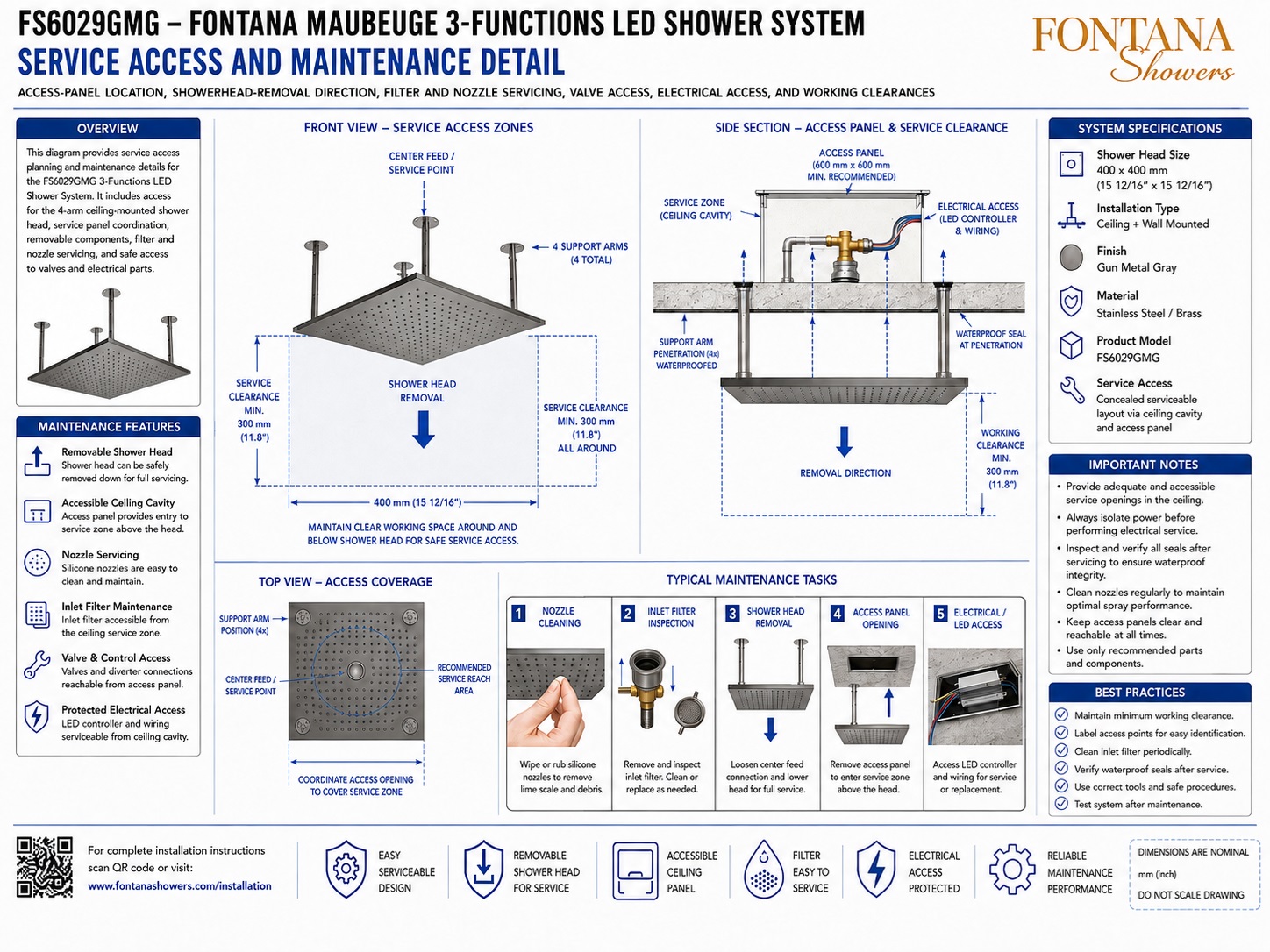
Shows the complete maintenance strategy for the large rain shower system, including the service-access panel, removable rain head, hand shower, body jets, thermostatic or pressure-balance valve, diverter controls, filters, check valves and optional electrical components. This drawing provides the primary reference for long-term service planning.
Access Panel Location
Illustrates a centrally located removable access panel behind the principal valve and control assembly. The drawing indicates an approximate panel width of 500–600 mm, a minimum lower clearance of about 300 mm above finished floor and an illustrated service zone extending to approximately 1200 mm.
Rain Shower Head Removal
Shows a typical three-step removal sequence: loosen the retaining set screw, rotate the shower arm or threaded connection counterclockwise, then lower the shower head straight down while supporting its weight to avoid damage to the fixture or surrounding finish.
Rain Head Filter & Nozzle Servicing
Describes routine rain-head maintenance including removal for deeper cleaning, descaling of mineral deposits, soft-brush cleaning of silicone nozzles, thorough rinsing and reinstallation after sealing surfaces and connection points are checked.
Hand Shower Servicing
Shows the hand-shower faceplate and internal filter as serviceable components. The filter can be removed, cleaned and rinsed before the unit is reassembled, helping maintain consistent flow and spray performance.
Body-Jet Servicing
Illustrates body-jet disassembly for maintenance. The jet face can be removed, the internal filter cleaned, accumulated debris flushed and the body jet then reinstalled and tightened securely.
Valve & Component Access
Shows access to the thermostatic or pressure-balance valve, diverter / flow-control valves, check valves, filters and water-supply connections. Adequate panel dimensions should permit leak checks, cartridge service and connection inspection without disturbing tile or permanent wall finishes.
Electrical Access — If Applicable
Coordinates a separate serviceable enclosure for optional LED controller, transformer, waterproof cable entries and wiring connections. Electrical components should remain dry, accessible and isolated from power before inspection or maintenance.
Working Clearances & Maintenance Schedule
Identifies typical minimum working clearances of approximately 600 mm around the service area and a nominal 2100 mm vertical reference to floor. The guide also recommends periodic nozzle, filter, valve and electrical inspections based on system use and water quality.
Engineering note:
Service access should be coordinated during design rather than added after
construction. Final panel dimensions, cartridge-removal space, rain-head
removal clearance, electrical access and maintenance intervals should be
verified against the actual system configuration, approved product
documentation and project-specific maintenance requirements.
Architectural, Plumbing and Maintenance Coordination Considerations
Access Panel Construction
Use a waterproof and corrosion-resistant access panel with a secure latch or push-to-open mechanism and maintain a small perimeter gap so the panel can be removed without damaging adjacent finishes.
Non-Splash Location
Locate the service panel outside the primary splash zone where practical while keeping it close enough to the valve and control assembly for direct maintenance access.
Cartridge Removal Space
Provide sufficient depth and frontal clearance so thermostatic, pressure-balance and diverter cartridges can be removed without dismantling permanent wall construction.
Shower-Head Removal Zone
Keep the area beneath and around the rain head unobstructed so the head can be supported, rotated and lowered safely during cleaning or replacement.
Electrical Separation
Where LED lighting or controls are installed, coordinate a dry service location for the controller, transformer and wiring connections and isolate power before maintenance.
As-Built Documentation
Record final access-panel locations and concealed component positions on as-built drawings so future maintenance personnel can locate serviceable equipment quickly.
FontanaShowers Installation and Specification Resources
FontanaShowers Product Catalog
Product information and technical resources for Fontana large rain shower systems, hand showers, body jets, valves and related accessories.
FontanaShowers Installation Resources
General installation and maintenance information for shower systems, concealed valves, service access and associated components.
Large Rain Shower Systems
Explore related multi-function shower configurations and coordinated serviceable components for commercial and residential installations.
BIM and Design Resources
Architectural coordination resources supporting project documentation and multidisciplinary shower, plumbing and service-access model development.
Shower Valves and Controls
Reference thermostatic valves, diverter controls, check valves, filters and serviceable concealed assemblies used in multi-function showers.
Shower Accessories and Service Parts
Review hand showers, body jets, hoses, cartridges, filters and related components used during maintenance and replacement work.
Professional Engineering and Maintenance References
Project verification:
Service-access and maintenance drawings are coordination tools and do not
replace approved project submittals or manufacturer instructions. The architect,
plumbing engineer, contractor, facility manager and qualified service personnel
should verify access-panel dimensions, component locations, cartridge-removal
space, working clearances, electrical isolation, maintenance procedures,
replacement-part compatibility and locally adopted plumbing and electrical
requirements before construction and before servicing the system.
|
|
|