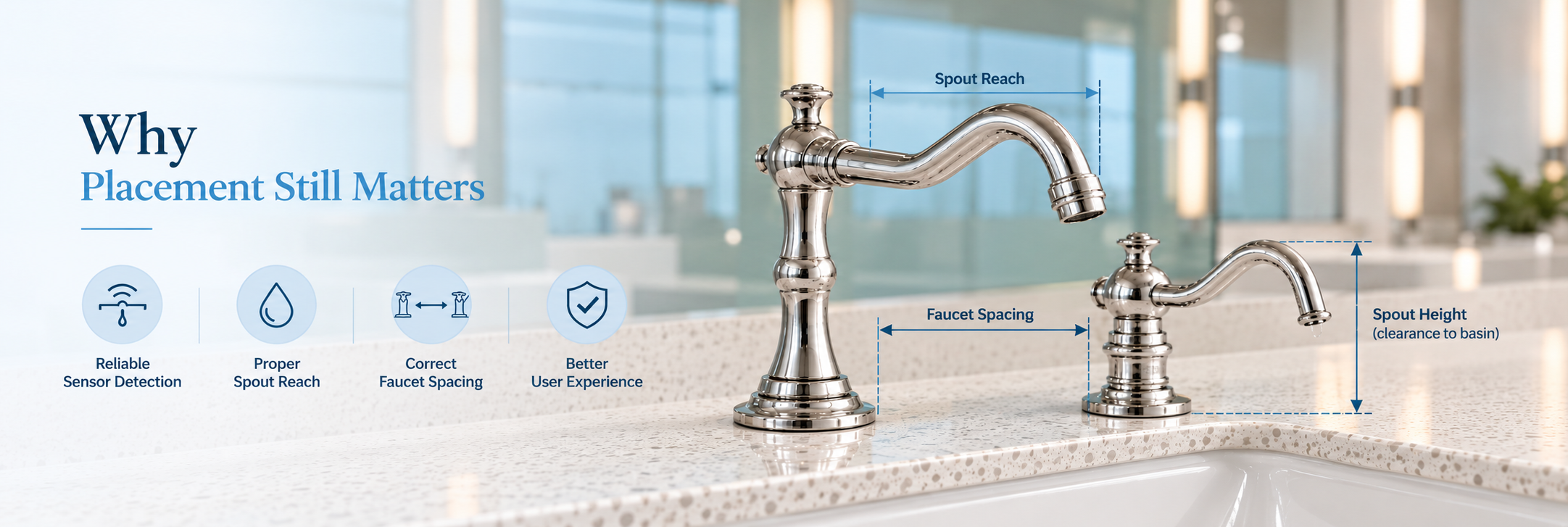
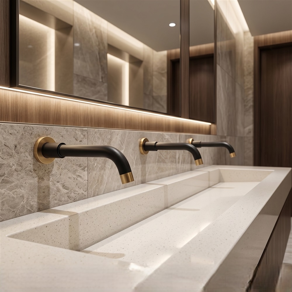
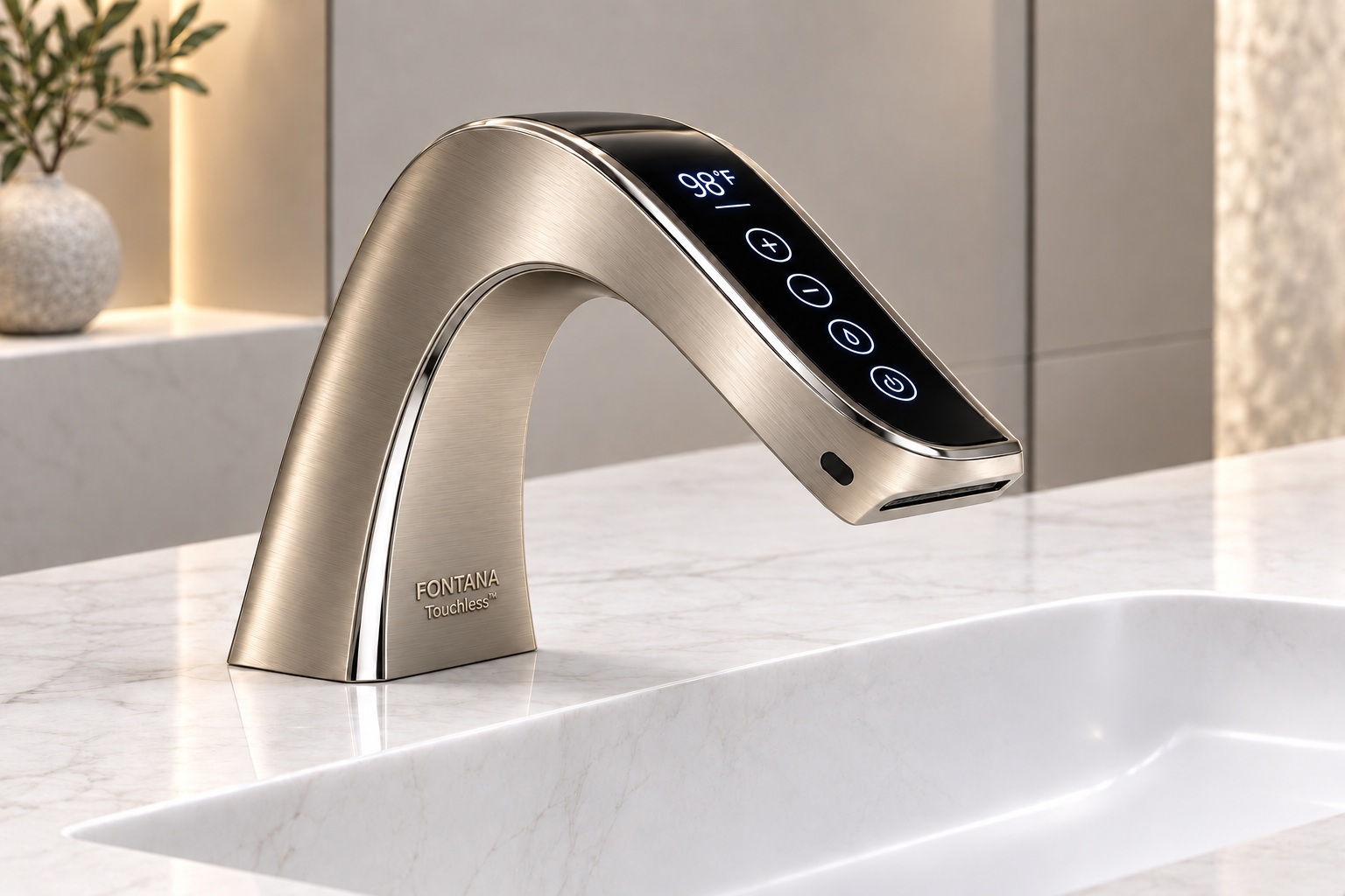
ToF Touchless Faucets: A More Predictable Experience
A well-coordinated washstation responds where hands naturally arrive. Time-of-Flight sensing provides distance information that can help a faucet controller distinguish the intended washing area from surrounding surfaces.
For architects and engineers, the specification task is to connect that measurement with basin geometry, user approach and documented control settings.
Explore Technical Insights
Optical ToF estimates distance from the travel time or phase shift of emitted light. Many ToF systems use infrared light; the useful distinction is distance measurement versus conventional reflected-intensity proximity detection.
Range alone does not define the full detection volume. Field of view, sensor orientation and optical signal quality also matter. See the IR versus ToF engineering comparison when evaluating the selected model.
Evaluate the assembled station against the way people approach, wash and withdraw their hands.
Coordinate the Target Area
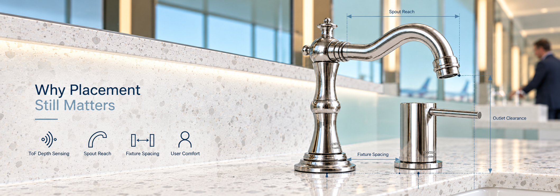
Locate the useful detection area beneath the outlet and within the basin. Maximum sensing reach is not a design objective by itself.
View More
Show spout projection and sensor direction on the fixture detail.
Check hand positions against the basin rim and water-impact location.
Test an empty basin and movement at adjacent stations.
Review the Decision Logic
Ask which settings govern detection, continued operation and release. Available adjustments vary by sensor and controller.
View More
Request supported range limits and setup procedures.
Confirm whether validation timing or separate entry and release thresholds are available.
Document timeout behavior and recovery after a blocked target.
Verify Water Response
Evaluate the complete response from hand entry to water delivery. Sensor acquisition and visible flow are different events.
View More
Record onset and shutoff over repeated use cycles.
Check performance under the intended supply and power conditions.
Agree acceptance criteria using the selected model’s documentation.
Assess Optical Conditions
Review the sensor’s view of the finished room, including direct daylight, reflective surfaces and dark basin finishes.
View More
Evaluate the actual material samples and proposed lighting arrangement.
Keep mirrors and reflective trim in the review of background targets.
Ask how the selected system handles weak or invalid distance readings.
Coordinate Power Interfaces
Record the power arrangement alongside the faucet schedule so electrical provision and control access are resolved before installation.
View More
Confirm the specified supply, connector type and permitted cable routing.
Identify which stations share a supply and how faults are isolated.
Verify restart behavior after a power interruption using manufacturer instructions.
Control Configuration Changes
Retain the approved setup as a project record. A replacement sensor or revised basin can require the station to be checked again.
View More
Record model, controller revision and accessible settings where supplied.
Identify the approved basin and mounting detail.
Recheck operation after substitutions that alter geometry or control components.
Translate these decisions into the fixture schedule, basin detail and commissioning record. The architectural specification resource and BIM and Revit library provide routes to supporting documentation; verify that drawings and data match the exact configuration being procured.
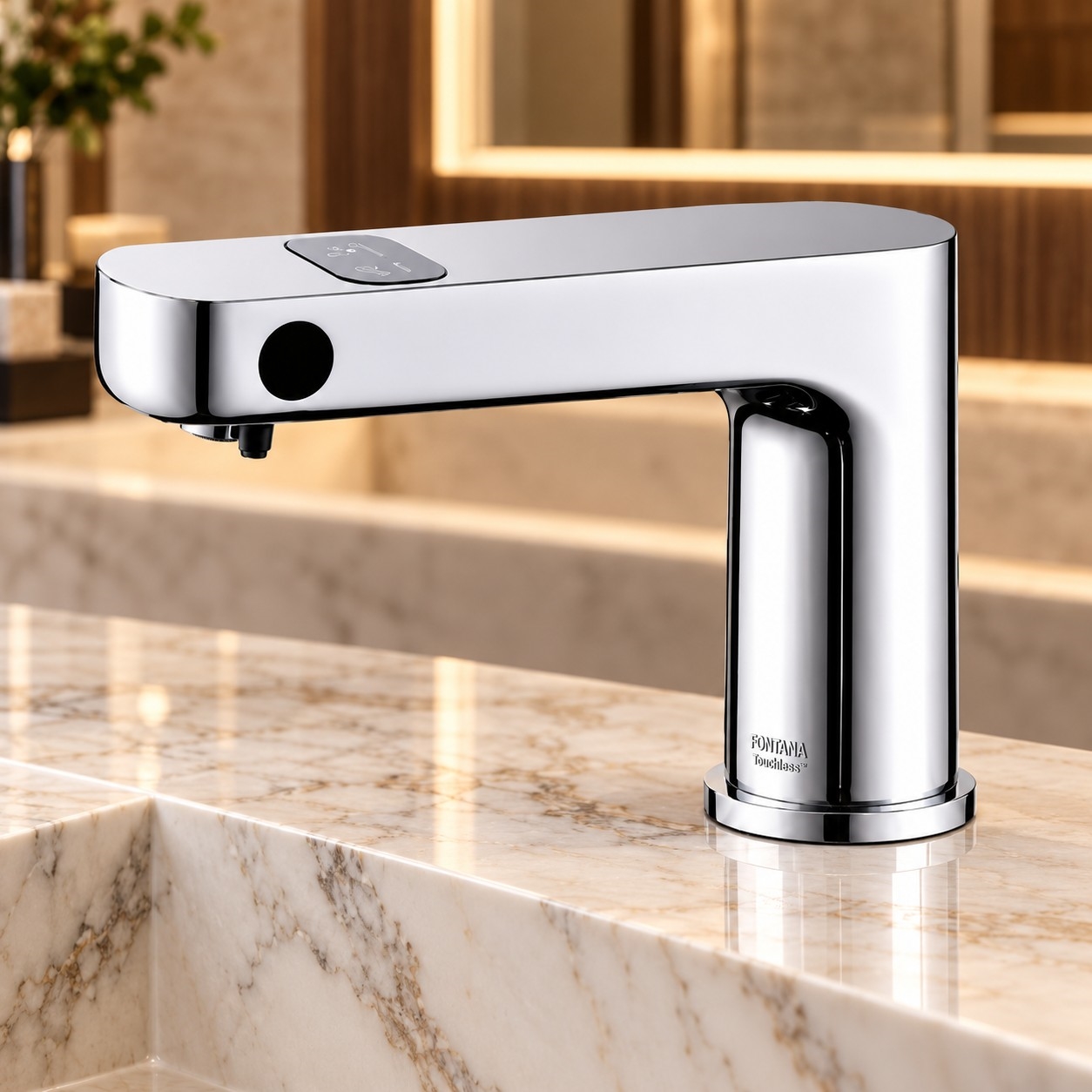
Coordinate the visible fixture with the basin, optical environment and concealed services.
Fixture Selection
Browse More Products
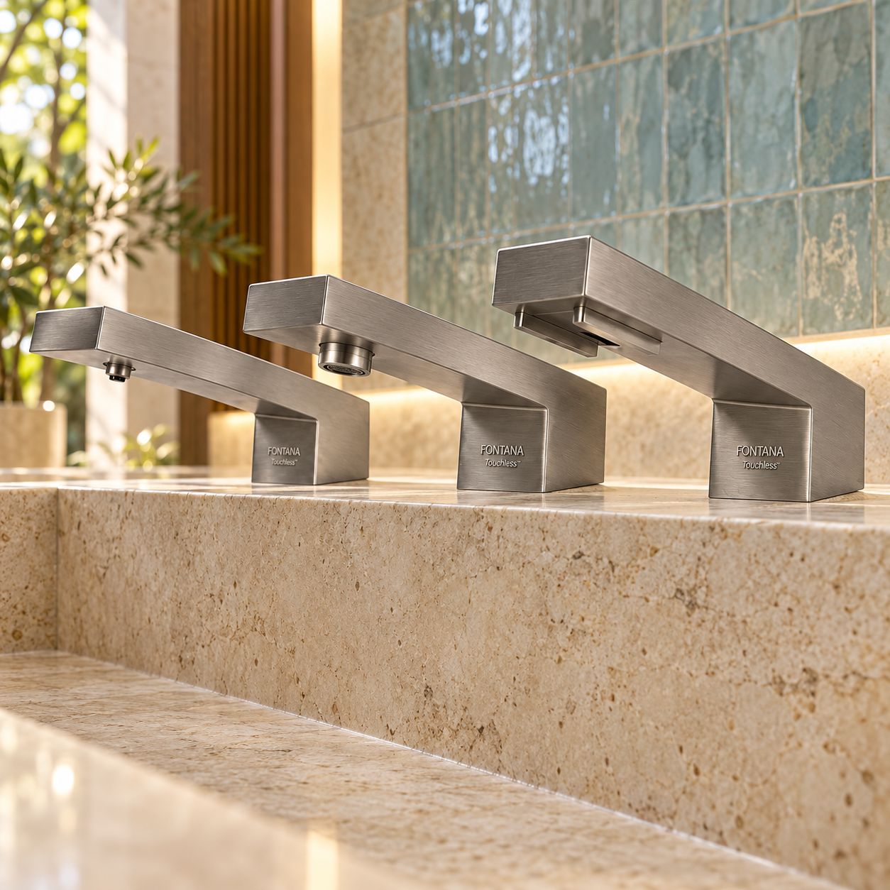
Compare fixture families, then confirm sensor type, mounting dimensions, power and outlet specifications at model level.
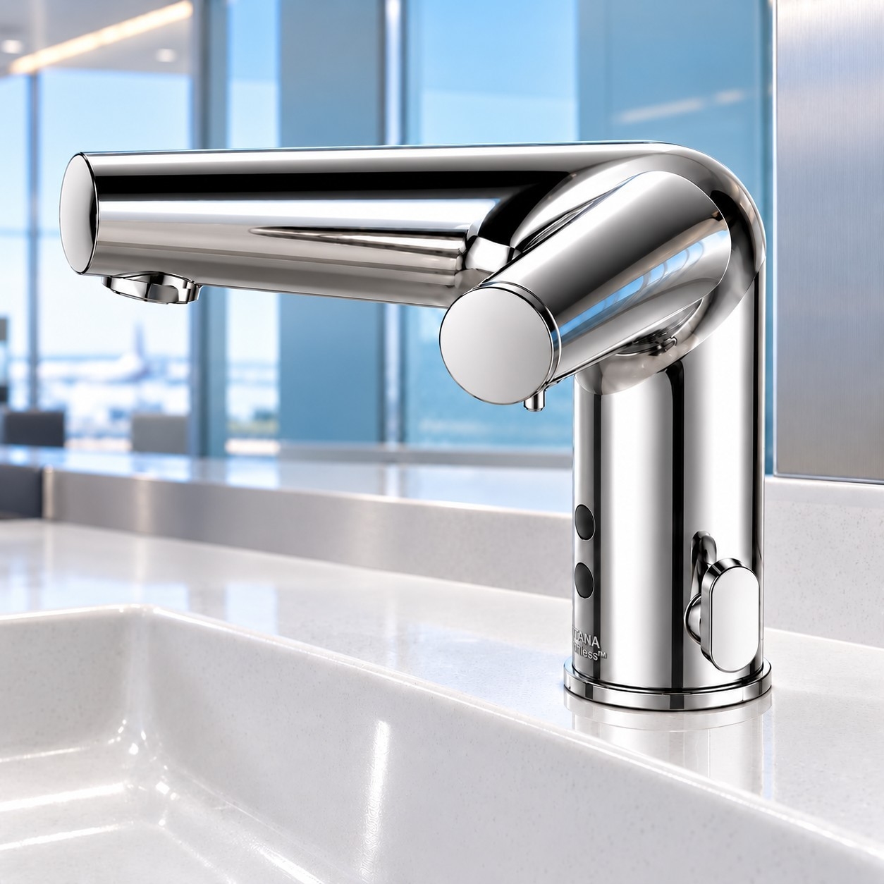
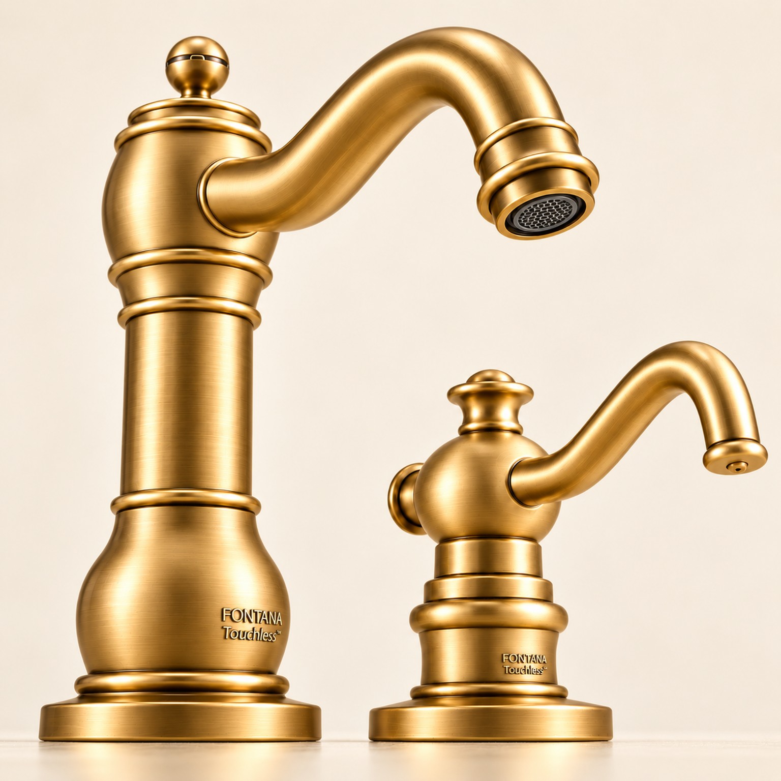
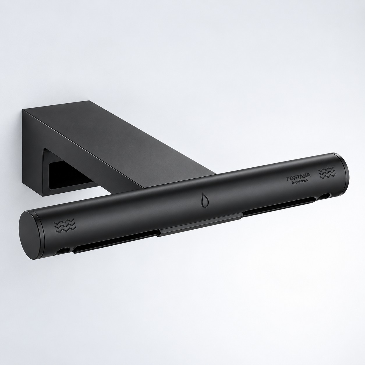
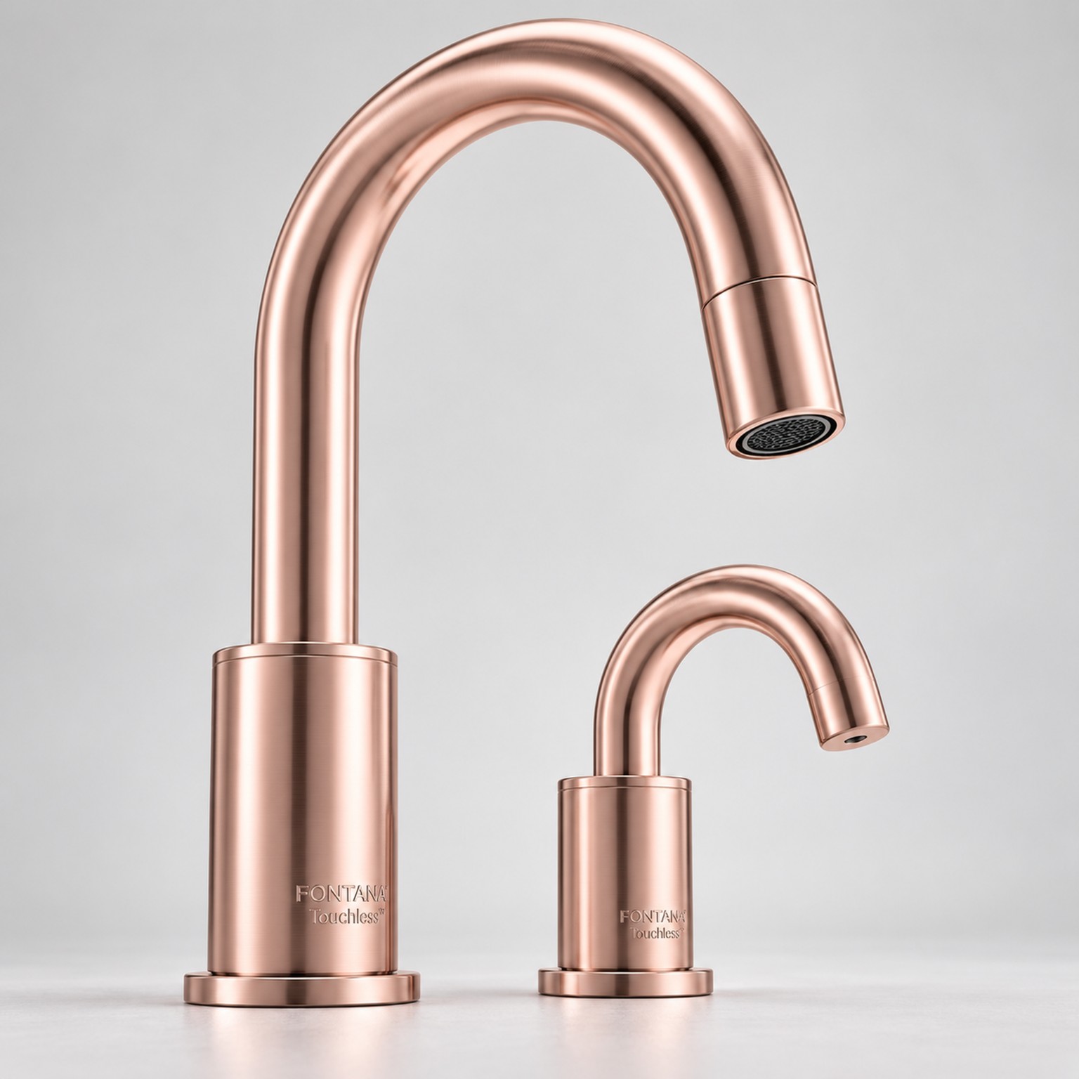
Touchless Faucets
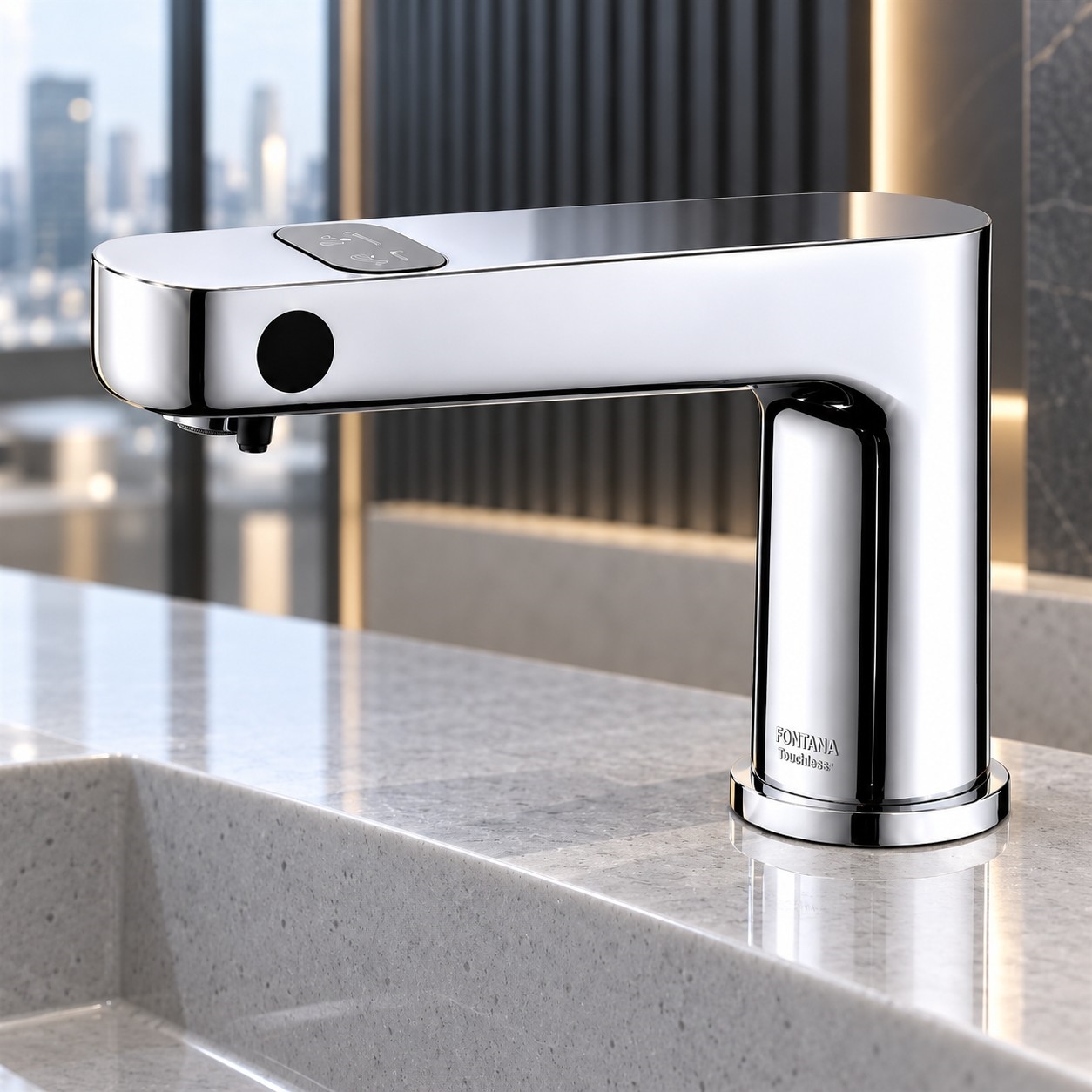
Review sensor-operated designs for coordinated commercial washstations.
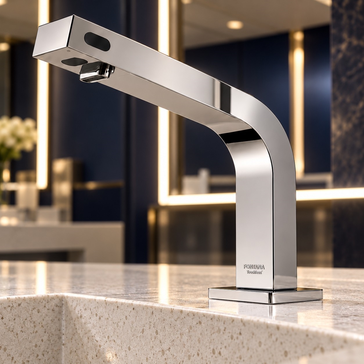
Specification Notes
Check the individual model’s sensing method, available adjustments and stated operating conditions before selection.
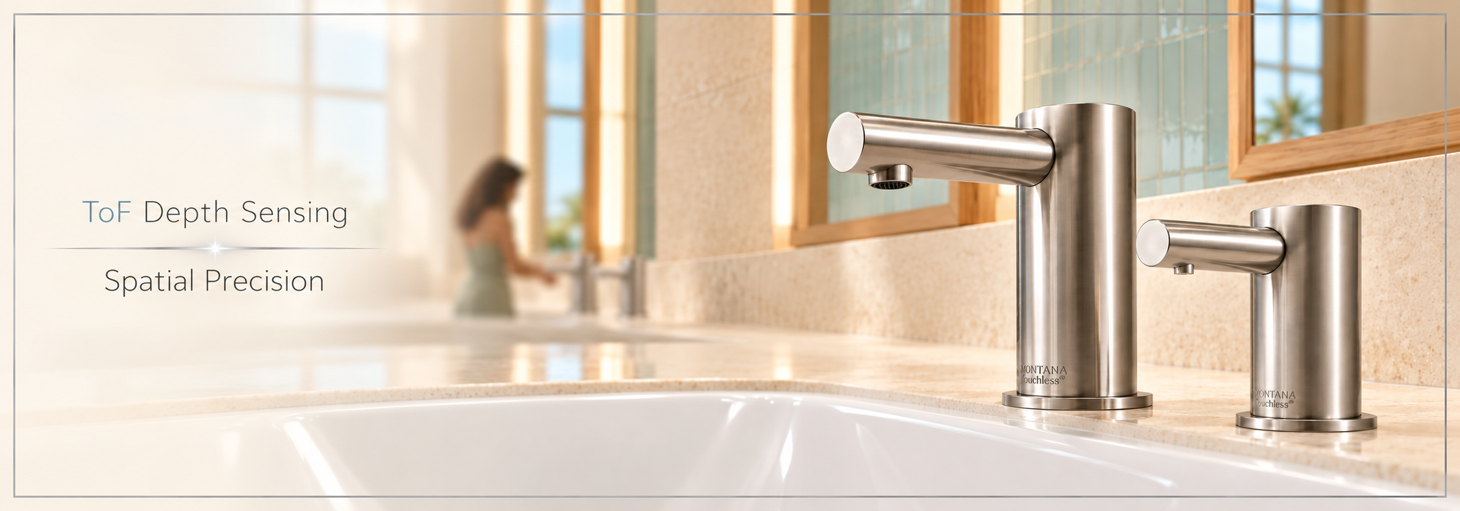
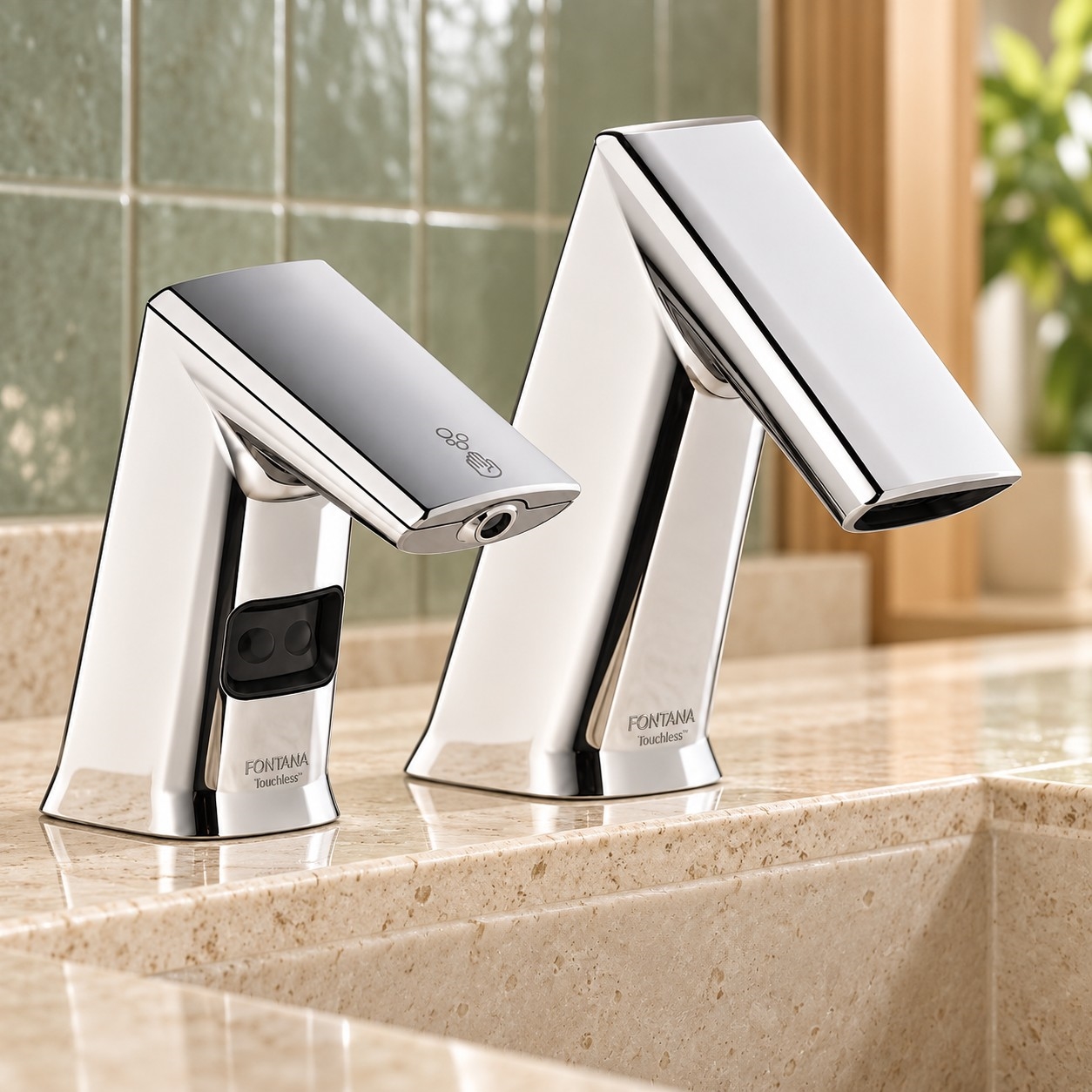
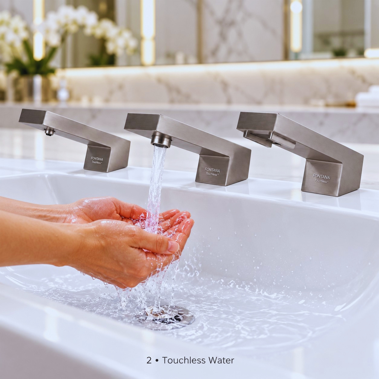
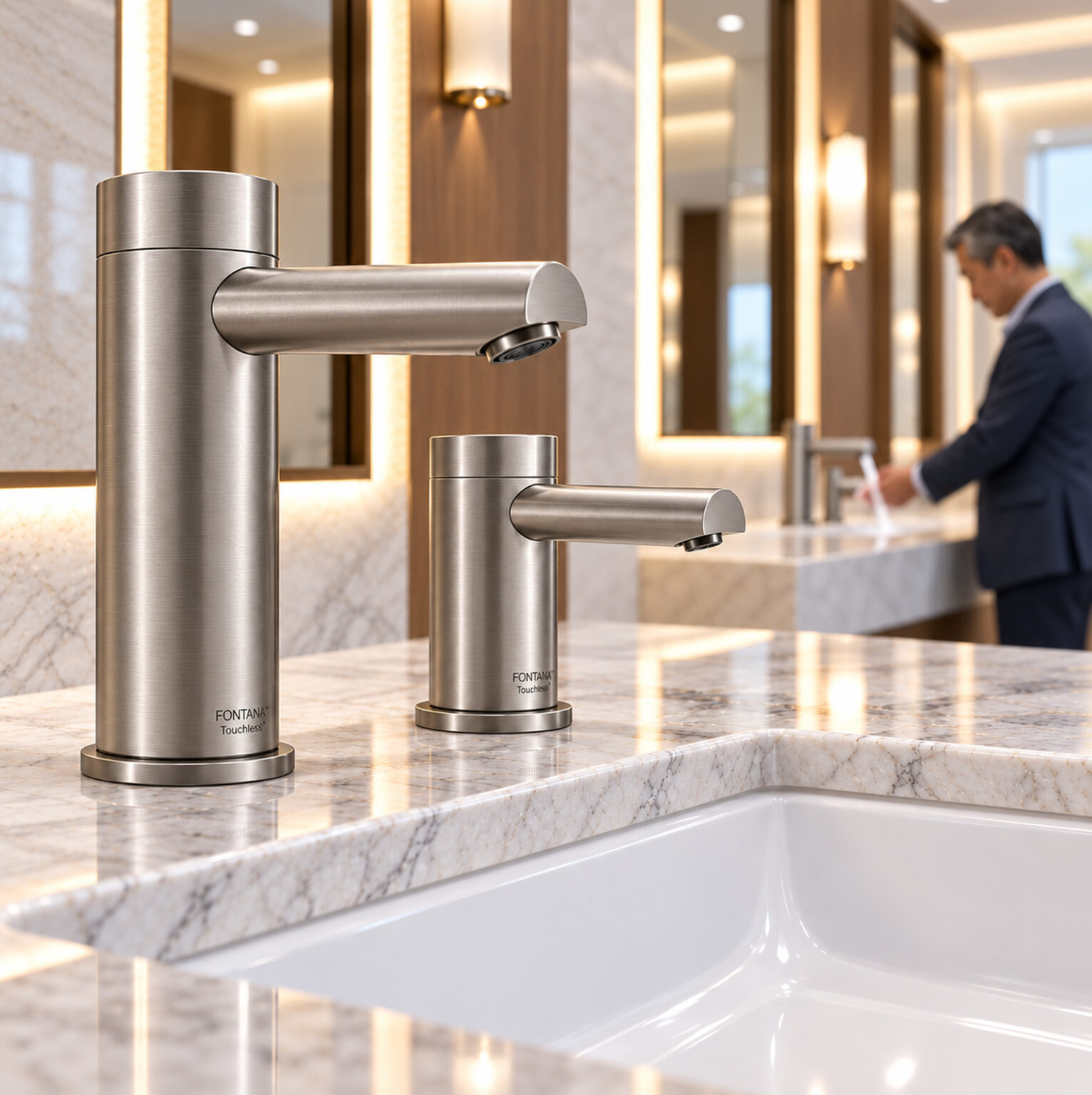
Evaluate the faucet and raised basin as one coordinated geometry, including rim height and outlet reach.
Specification Notes
Confirm that the rim does not obstruct normal hand movement. Verify splash behavior and sensor acquisition with the scheduled basin rather than a substitute.
How Time-of-Flight Sensing Supports Controlled Activation
Optical ToF sensing estimates target distance from the timing or phase relationship of emitted and returned light. The faucet controller uses that information to evaluate whether a target is within its operating zone. Distance measurement does not by itself authorize water flow: the installed system must also qualify the measurement and apply its activation, release and timeout logic. Fontana’s ToF sensor engineering discussion provides context for selecting and evaluating distance-based sensing.
A useful ToF activation zone is a three-dimensional relationship between the sensor’s optical view and the user’s handwashing position. A distance threshold cannot compensate for a sensor aimed toward an unsuitable surface. Coordinate basin depth, spout projection and mounting angle using the detection-zone planning guide, then verify the final assembly with both an empty basin and realistic hand positions.
Activation Boundary
Confirm supported range settings and map the useful washing area. Test hands entering from the front and sides, along with partial withdrawal. Record any gap between the comfortable washing position and the position required to maintain flow. Maximum component range is not the appropriate default activation distance.
Optical Conditions
Include daylight, reflective surfaces and an optically clean sensor window in baseline testing. Repeat the inspection after normal cleaning. Where diagnostics are available, distinguish invalid measurements from valid out-of-zone targets instead of treating both as the same event.
System Response
Measure the complete hand-entry-to-water sequence. Separate sensing delay, presence qualification and hydraulic response during diagnosis. A responsive distance sensor does not prove that the installed valve, supply arrangement and controller deliver equally prompt water onset.
Release Behavior
Withdraw hands fully and record the time until flow ceases. Repeat with slow and rapid movement near the activation boundary. Investigate repeated cycling, residual dripping and sustained flow separately; they can originate in control decisions, hydraulic drainage or a valve fault.
Adjacent Fixtures
Operate neighboring stations independently and simultaneously. Include pass-by movement and hands crossing between basins. Document physical sight lines before attributing unexpected activation to optical interference. Repeat the test with the scheduled mirrors, partitions and lighting installed.
Service Conditions
Record approved cleaning methods, controller access, power arrangement and replacement procedures. After optical-window, controller or faucet replacement, follow the manufacturer’s setup requirements and repeat the original station acceptance checks.
ToF Range and Valve Command: An Illustrative Sequence
The graph separates a measured target entering an activation band from the controller’s later valve command. It illustrates why detection, qualification and release should be evaluated separately. The axes are normalized; this is not measured Fontana performance.
Conceptual control sequence only. The illustrated distances, delays and filtering behavior are not product specifications. A valve command is distinct from measured water flow.
Distinguish Measurement from Actuation
For commissioning, define separate timestamps for hand entry, controller recognition, valve command and visible water onset. If internal events are unavailable, record only observable entry-to-flow and withdrawal-to-stop intervals. Do not infer internal processing time from an external video alone.
Evaluate Repeatability as Well as Average Response
A proposed test report should list the number of trials, test conditions, typical response and the slowest observed response. Record missed starts, unintended starts and interrupted washing as distinct outcomes. Repeating an identical sequence makes it easier to determine whether a change to placement or an approved setting improves operation.
Separate Sensor Logic from Water Delivery
If the controller recognizes hands consistently but water onset varies, investigate the valve, supply and outlet arrangement. If recognition itself varies, investigate detection geometry and optical conditions first. Use manufacturer-approved diagnostic methods; the graph does not prescribe firmware settings for a particular faucet.
Commission the Complete ToF Washstation
Establish a repeatable acceptance check using the scheduled ToF faucet, basin, mounting position and final lighting. Record whether the empty station remains inactive, hands are recognized throughout the intended washing area, and flow stops after withdrawal. Repeat with neighboring stations operating. Compare observations with the selected model’s documented settings and project criteria rather than applying a single response-time or detection-distance value to every ToF faucet.
Accessibility must be assessed at the complete installation. Coordinate approach space, knee and toe clearance, fixture height and operable parts using the U.S. Access Board’s lavatory and sink guidance. ToF sensing alone does not establish an accessible washstation. Verify that the intended approach places hands within a usable detection zone.
AEC Coordination Matrix for ToF Touchless Faucets
Coordinate the ToF detection zone across architectural placement, plumbing installation, electrical provision and commissioning. Each discipline should resolve its interface before the final operational test.
ToF coordination diagram: a project-planning illustration, not a manufacturer wiring or installation drawing.
Proposed ToF Coordination and Handover Schedule
Discipline
Coordinate
Record at Handover
Architecture / Interiors
Spout projection, basin profile, mounting position, mirrors and comfortable hand placement.
Approved installed dimensions and photographs of the usable ToF activation area.
Plumbing
Model-specific supply requirements, outlet, valve orientation, isolation and service access.
Water-onset and shutoff observations, operating conditions and leak inspection.
Electrical
Approved power source, connections, cable routing and accessible replacement provisions.
Power configuration and observed startup and recovery behavior under approved test procedures.
Commissioning
Empty-basin rejection, hand entry, boundary movement, withdrawal and simultaneous station use.
Settings, test sequence, trial count, exceptions, corrective actions and retest results.
Facilities
Optical-window cleaning, fault reporting, replacement parts and post-service verification.
Maintenance instructions and the approved baseline against which later changes can be compared.
Assign responsibility for confirming the final detection zone. A faucet substitution, different basin or changed mounting dimension should trigger a coordination review and repeat testing. Record the installed model and available settings rather than relying on a generic “ToF sensor” description.
Keep service access compatible with the accessible approach space. A controller or power supply that can be reached only by obstructing required clearances creates a coordination problem even when the sensor operates correctly.
Separate ToF Sensing Performance from Water Efficiency
Distance-based activation does not determine rated flow. Water consumption also depends on the outlet, operating duration, supply conditions, leaks and unintended activations. Use EPA’s commercial faucet water-efficiency guidance when evaluating the installed ToF washstation. Any claimed water savings require an appropriate baseline and measured operating data; ToF technology alone does not establish a savings percentage.
Technical FAQs: ToF Touchless Faucet Engineering
These questions address sensor integration and proposed commissioning checks. Available diagnostics, algorithms and adjustments depend on the selected faucet. Semiconductor references explain underlying technology; they do not identify the component installed in a Fontana model.
A reported distance and an acceptable measurement are separate concepts. Some ToF devices expose range status and signal-quality information alongside distance. The host must interpret those outputs using the component documentation before treating the reading as a target inside the activation zone.
As a proposed diagnostic procedure, log valid in-zone, valid out-of-zone and invalid results separately where the faucet provides access. Ask the manufacturer how loss of valid measurements affects an already-open valve, how recovery is handled, and whether a maximum-run limit remains active. Do not assume that an invalid reading means either zero distance or confirmed hand withdrawal.
Measurement timing budget and the interval between measurements are distinct parameters in sensors that expose both. Their allowed relationship is device-specific. Faucet firmware may additionally qualify several results before changing valve state.
Requiring several qualifying measurements can delay activation, while shorter sampling intervals can change how quickly a controller recognizes hand entry. Evaluate the documented control sequence together with processing and valve response; these effects do not establish a universal ToF faucet response time.
During testing, measure hand-entry-to-visible-flow directly. Record supply conditions and repeat the sequence. Request manufacturer timing documentation before changing any supported setting, because faster sampling alone does not establish reliable target qualification.
Range gating evaluates distance along the optical viewing direction. Field of view describes angular coverage. Some ToF components also support a programmable receiver region of interest, or ROI, which changes the effective viewing region. These controls are not interchangeable, and a faucet may expose none of them to the installer.
The optical viewing region generally widens farther from the sensor. Actual detection coverage also depends on the optics, target position and signal acceptance. Review the manufacturer’s detection information, then confirm the usable washing area with the installed faucet and basin.
Request the faucet’s supported geometry and approved setup method. A semiconductor’s maximum range or programmable ROI does not establish equivalent capability in the finished faucet. See the ST ToF component datasheet for an example of device-level field-of-view and ROI features.
Optical crosstalk can occur when emitted light reaches the receiver through reflections associated with the protective window rather than the intended target. Window geometry, optical transmission and separation of emitter and receiver paths influence integration. Offset correction and crosstalk compensation address different effects.
For maintenance, begin with the approved cleaning procedure and inspect for residue, damage or a changed optical assembly. Do not compensate for a dirty or damaged window by arbitrarily extending the activation distance. After replacement, use the manufacturer’s prescribed setup or calibration process and repeat the station’s acceptance tests.
As a proposed verification sequence, hold hands near the edge of the useful detection area, move slowly across it, then withdraw completely. Record repeated valve cycling, interrupted washing and delayed shutoff separately. Repeat at several entry angles and with the final basin wet and dry.
Ask whether the selected controller uses separate activation and release thresholds, temporal qualification or another stabilization method. Such methods can trade responsiveness against resistance to brief disturbances. They are design choices to verify, not features to assume from the ToF label.
Establish an agreed pass condition for comfortable continuous washing and complete withdrawal. Retest after each approved change, recording the setting and physical arrangement so that later service work can reproduce the result.
Use a controlled comparison: test one station with neighbors idle, repeat with neighbors operating, then repeat the original condition. Keep lighting, hand trajectory and basin condition consistent. Record which station starts unexpectedly and whether the event follows a visible target, neighboring use or a power disturbance.
Do not diagnose optical interference solely from simultaneous activation. Overlapping sight lines, reflections and shared electrical conditions should be investigated separately. Request manufacturer support where internal diagnostics are required.
Under the approved service procedure, verify startup and recovery with the basin empty and with hands present. Document whether settings persist and whether commissioning is required after power restoration. Confirm expected behavior for the specific power and valve configuration rather than assuming all ToF faucets recover identically.
ToF touchless faucet selection should connect distance-based sensing with the actual handwashing task. Review why Fontana selected Time-of-Flight sensing alongside the manufacturer’s technical discussion of ToF faucet sensing. Define the intended activation area, coordinate the basin and mounting position, and verify consistent recognition and release in the completed restroom.
For commercial ToF washstations, combine sensor evaluation with the U.S. Access Board’s accessibility guidance and EPA’s commercial faucet water-efficiency guidance. Coordinate user approach, usable detection geometry, rated flow, shutoff behavior and service access. These resources guide installation review; they do not certify a faucet merely because it uses ToF sensing.
Response Architecture
What Happens Between Hand Entry and Water Flow?
Review the entire control path. A sensor response claim describes only part of the experience at the outlet.
Optical AcquisitionReceive reflected light and estimate target distance.
Target ValidationApply supported range, confidence and timing criteria.
Valve CommandConvert the accepted detection into an electrical actuation signal.
Water DeliveryObserve the valve and water path produce usable outlet flow.
Conceptual response sequence. Box widths do not represent measured duration; implementations vary by model.
The architect defines where the user should wash; the engineer coordinates the operating conditions; the contractor realizes the assembly. A responsive result depends on the interfaces between those decisions, not simply a sensor’s advertised range.
Range Is Not Field Width
A distance setting limits depth. Optical field of view determines the lateral region in which a target may be acquired.
Control the Optical Path
The protective window is part of the ranging assembly. Unwanted reflected light can influence the signal reaching the receiver.
Separate Timing Events
Detection, valve command and visible water onset are distinct events. An acceptance test should state which event starts and ends the measurement.
Submittal Review
Specify Evidence, Not Sensor Labels
A useful technical submittal identifies what is supplied, what can be adjusted and how the installed result will be accepted.
Suggested coordination record for a ToF faucet installation
Review Item
Request With the Submittal
Project Check
Detection geometry
Sensor location, supported range settings and field-of-view information where available.
Compare the useful detection area with the basin section and intended hand position.
Control sequence
Activation, release, timeout and restart behavior; adjustment method.
Agree how normal use, hand withdrawal and prolonged detection will be demonstrated.
Water delivery
Rated flow, operating pressure range, outlet type and mixing arrangement.
Coordinate supply conditions and temperature control independently of the sensor specification.
Electrical interface
Power requirements, supply components, connections and installation instructions.
Confirm routing and access without conflicts with supports, traps or accessible clearances.
Installation record
Approved model, mounting dimensions, final settings and commissioning results.
Retain a reference for repeated stations and subsequent component substitutions.
A BIM object establishes coordination geometry, but it does not demonstrate sensing performance. Pair the digital fixture model with the selected product’s technical data and an installed mock-up when the basin, lighting or mounting arrangement is unusual.
Carry the approved design intent into a documented installation and commissioning record.
Commissioning Strategy
Verify ToF Activation, Shutoff and Shared-Station Performance
A single successful activation does not describe how the station behaves throughout handwashing. Build the acceptance check around transitions: an empty basin, hands entering, hands moving within the wash area, withdrawal and return to idle.
Idle to Activation
Begin with an empty station. Observe whether natural hand entry produces water without requiring a deliberate search for the sensor.
Activation to Release
Move hands through the useful washing area, then withdraw. Look for unwanted interruptions and inconsistent water termination.
Single to Shared Use
Operate neighboring fixtures together to check whether the approved arrangement remains usable during normal shared-counter activity.
AEC Coordination Matrix
One Washstation, Three Technical Perspectives
Suggested coordination responsibilities. Confirm contractual scope and review ownership for the project.
Design intent, engineering inputs and installation evidence
Interface
Architect / Designer
MEP Engineer
Contractor / Installer
Basin and spout
Set basin geometry, mounting plane and intended hand position.
Coordinate outlet delivery and supply requirements.
Verify actual dimensions before drilling or rough-in.
Sensor environment
Identify mirrors, finishes, daylight and neighboring stations.
Request supported detection settings and system limitations.
Check the finished arrangement under actual lighting.
Power and controls
Provide coordinated enclosures and unobstructed access.
Define supply provision and circuit grouping as applicable.
Confirm connections, component locations and restart behavior.
Accessible use
Coordinate approach, clearances and user reach.
Review fixture controls and related services.
Verify the installed assembly preserves required clearances.
Acceptance record
Confirm the result supports the intended user experience.
Agree measurable performance criteria.
Record settings, test conditions and outstanding adjustments.
Resolve Substitutions Before They Reach the Countertop
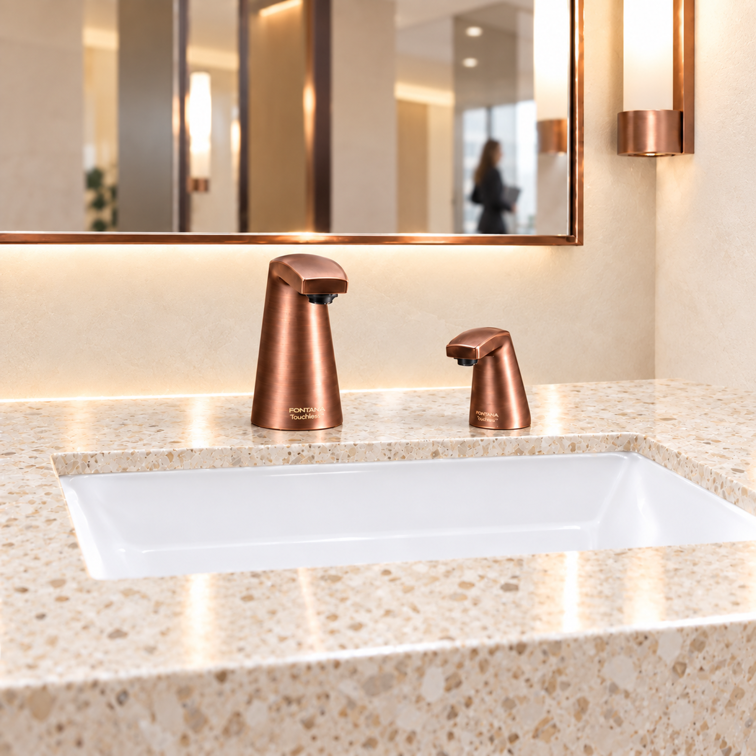
A visually similar replacement can change sensor location, spout projection, power provision or mounting depth. Compare those interfaces explicitly before approval. Retain the revised cut sheet and update the basin detail when the approved geometry changes.
Project Requirements
Connect Sensing With the Complete Installation
A detection zone should be usable from the intended approach position. Coordinate clear floor space, knee and toe clearance, fixture height and operable parts with the U.S. Access Board’s lavatory guidance. Automatic activation alone does not establish accessibility compliance.
Assess water delivery separately from sensor selection. Rated flow, operating duration and unintended activation influence consumption; use EPA’s commercial faucet guidance for facility water-use planning. Government references inform project review and do not certify the illustrated fixtures.
Can one sensor setting be used across every basin?
Do not assume a common preset is suitable where basin depth, spout height or sensor orientation changes. Confirm each distinct faucet-and-basin arrangement, then document which stations share the approved configuration.
Does ToF sensing establish the faucet’s flow rate?
No. Sensing governs the control decision; the outlet, valve and supply conditions determine water delivery. Review the rated flow and relevant pressure conditions separately in the product data.
What should a contractor receive before rough-in?
Provide the approved mounting detail, supply and power requirements, component locations and installation instructions. Resolve any mismatch between the architectural elevation, basin cutout and manufacturer’s dimensions before closing concealed work.
Can a dark basin be approved from a photograph?
A photograph cannot establish optical performance. Evaluate the actual surface, sensor orientation and available signal margin with the selected fixture. Dark appearance in visible light does not by itself quantify infrared reflectance.
Should a higher maximum range be preferred?
Not automatically. The useful range must support natural hand placement while excluding background surfaces and pass-by activity. Prefer documented suitability for the intended geometry over a larger maximum-distance number.
What should be recorded when a station behaves differently?
Record the fixture and basin models, mounting dimensions, power condition, final settings, light exposure and observed behavior. Compare against an equivalent station before attributing the difference to the sensing technology.
Find Out First
Get FontanaShowers emails of inspiration, new product releases, and more!


.png)