Fontana Multi-Function Shower Systems™ | Architectural and Engineering Resource
Fontana FS-Large Rain Shower Head System:
Water-Pressure, Flow and Pipe-Sizing Requirements
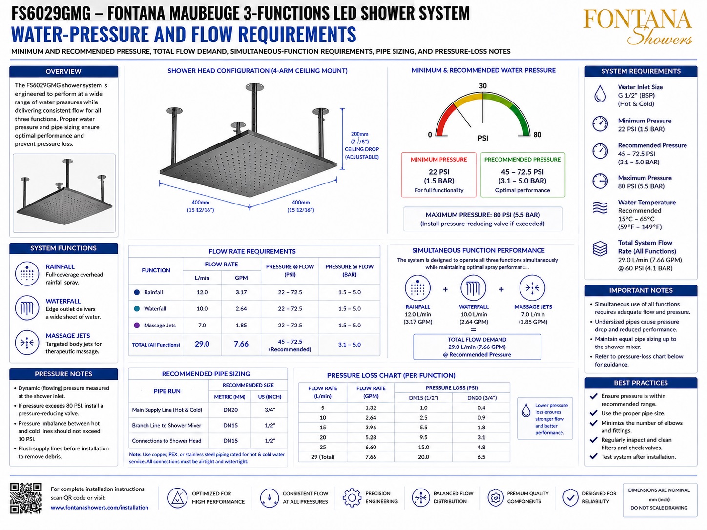
This hydraulic design resource is intended to support architects, plumbing
engineers, interior designers, contractors, installers and facility managers
coordinating the Fontana FS-Large Rain Shower Head System within residential,
hospitality and commercial shower environments. The drawing package communicates
the large rain head, hand shower, six body jets, thermostatic mixing valve,
diverter/distribution assembly, mixed-water supply arrangement, pressure range,
simultaneous flow demand, branch sizing, main-pipe sizing, estimated pressure
losses and recommended concealed service-access requirements.
Fontana FS-Large Multi-Function Rain Shower System
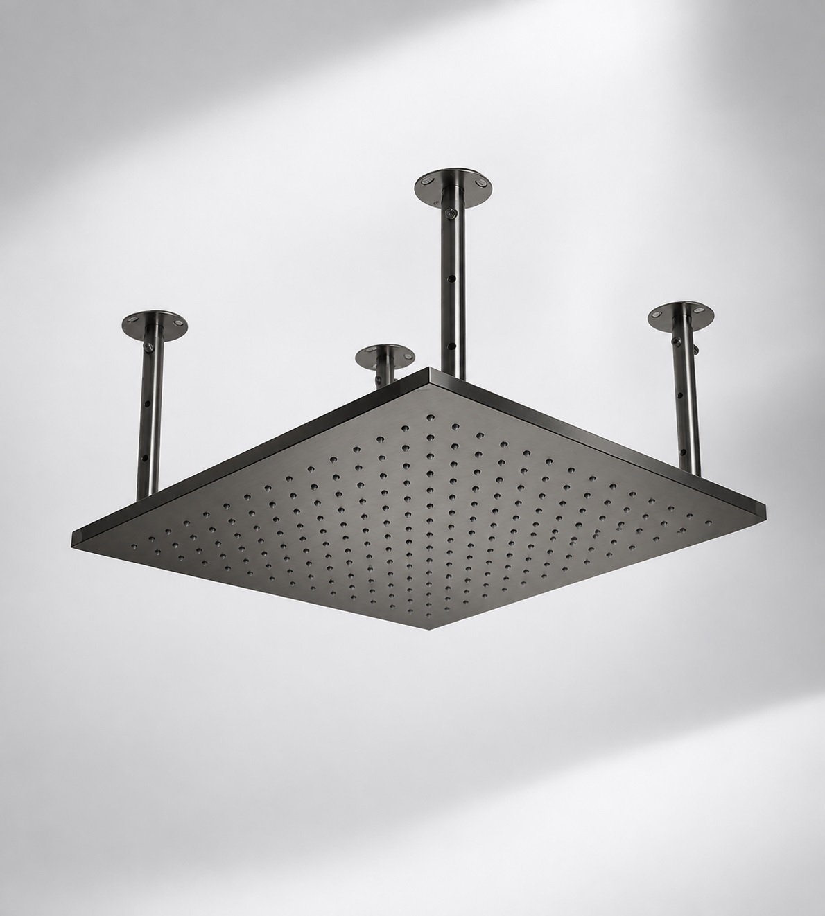
The Fontana FS-Large system combines a 400 mm rain shower head, hand shower,
six body jets, thermostatic mixing valve and distribution controls for
multi-outlet showering. Because several functions may operate at the same
time, the installation should be designed around dynamic pressure and
simultaneous flow demand rather than static pressure alone. Adequate pipe
sizing, service access and allowance for component pressure losses are
essential to stable performance.
-
System type:
Multi-function thermostatic shower system
-
Large rain head:
400 mm
-
Outlet package:
Rain head, hand shower and six body jets
-
Minimum operating pressure:
200 kPa (29 PSI)
-
Recommended working pressure:
300–500 kPa (43–73 PSI)
-
Maximum static pressure:
800 kPa (116 PSI)
-
Total simultaneous flow demand:
43.5–55.5 L/min (11.5–14.7 GPM)
-
Recommended mixed-water main:
3/4 in nominal
-
High-demand supply main:
1 in nominal recommended
-
Individual outlet branches:
1/2 in nominal
-
Recommended service opening:
600 × 600 mm (24 × 24 in.)
Required Water-Pressure and Flow Drawing Package
Each hydraulic drawing should use a consistent system identification block,
flow-unit convention and pressure reference. Pipe sizes should be shown as
nominal sizes, flow values should be stated in both L/min and GPM, and
pressure should be identified in kPa and PSI. The package should clearly
distinguish incoming hot and cold supplies, thermostatic mixing, mixed-water
distribution, individual outlet branches, simultaneous-function demand,
pressure losses and the concealed service zone.
System Pressure / Flow Schematic
Shows the hot- and cold-water supplies entering the thermostatic mixing
valve, the mixed-water outlet feeding the diverter/distribution assembly,
and the branch connections serving the rain head, hand shower and six
body jets. This schematic provides the primary hydraulic coordination
reference for the complete system.
Large Rain Head Flow
Identifies a nominal rain-head flow range of 18–22 L/min
(4.8–5.8 GPM). The available dynamic pressure at the outlet should be
checked after upstream valve, fitting and pipe losses are deducted.
Hand Shower Flow
Identifies a nominal hand-shower demand of 7.5–9.5 L/min
(2.0–2.5 GPM). The branch should be coordinated with hose length,
fittings and routing so avoidable pressure loss is minimized.
Body-Jet Flow
Shows six body jets with a combined nominal demand of 18–24 L/min
(4.8–6.3 GPM). Distribution should be balanced so the jet array receives
consistent pressure and comparable flow across the complete set.
Simultaneous-Function Demand
Summarizes expected combined flow for typical operating combinations.
All functions active require approximately 43.5–55.5 L/min
(11.5–14.7 GPM), which should be used when sizing the main supply and
mixed-water distribution for full simultaneous operation.
Pressure Range
Defines 200 kPa (29 PSI) as the minimum operating pressure,
300–500 kPa (43–73 PSI) as the recommended working range and
800 kPa (116 PSI) as the maximum static pressure. Dynamic pressure
at operating flow is the critical design reference.
Pipe-Sizing Detail
Shows 1/2 in nominal branch lines to individual outlets, a recommended
3/4 in nominal mixed-water main and a 1 in nominal main for long runs
or high simultaneous demand. Final sizing should reflect actual pipe
length, fitting count and available pressure.
Pressure-Loss Allowance
Indicates approximately 20–35 kPa (3–5 PSI) loss through the thermostatic
valve, 10–20 kPa (1.5–3 PSI) through the diverter/control assembly and
an additional 35–70 kPa (5–10 PSI) allowance for fittings, hoses,
outlets and branch routing.
Service Access
Identifies a recommended concealed service opening of 600 × 600 mm
(24 × 24 in.) centered on the mixer, diverter and manifold zone. The
access area should remain serviceable after finishes are installed.
Engineering note:
Published outlet flow values depend on available dynamic pressure. Simultaneous
use substantially increases total flow demand, and long runs, fittings,
valves, hoses, filters and elevation changes increase pressure loss. Final
pipe sizing and balancing should be verified against project-specific
hydraulic calculations and locally adopted plumbing requirements.
Architectural and Plumbing Coordination Considerations
Dynamic Supply Pressure
Verify pressure while the system is flowing, not only static line pressure.
The available pressure must remain sufficient after valve and piping losses.
Simultaneous Flow
Size the system for the intended combination of shower functions.
Where all outlets may operate together, use the maximum combined flow range.
Main and Branch Sizing
Coordinate the 1/2 in branches with an appropriately sized mixed-water
main. A 1 in main may be appropriate where demand or run length is high.
Pressure-Loss Control
Keep pipe runs as direct as practical and minimize unnecessary elbows,
restrictions, long hose runs and abrupt routing changes.
Hot-Water Capacity
Confirm the water-heating and storage system can sustain the required
mixed-water flow and temperature during simultaneous multi-outlet use.
Service Accessibility
Maintain accessible space around the thermostatic mixer, diverter and
manifold for commissioning, balancing, inspection and future maintenance.
FontanaShowers Installation and Specification Resources
Professional Engineering and Plumbing References
-
International Code Council – Plumbing Codes
Provides code context for water-supply sizing, shower installations,
valves, piping and fixture requirements.
-
IAPMO – Plumbing Standards and Codes
Provides plumbing-code and product-standard resources relevant to
water-supply systems, fixture installation and system safety.
-
American Society of Plumbing Engineers
Professional engineering reference for plumbing-system design,
water distribution and hydraulic calculation practices.
-
ASHRAE
Provides technical resources relevant to building water heating,
energy performance and coordinated building-services design.
-
EPA WaterSense
Provides water-efficiency information and conservation guidance
for plumbing fixtures and building water use.
Project verification:
Water-pressure and flow drawings are coordination tools and do not replace
approved project calculations or submittals. The architect, plumbing engineer,
contractor and licensed installer should verify dynamic supply pressure,
simultaneous flow demand, hot-water capacity, pipe sizing, thermostatic-valve
performance, diverter losses, branch balancing, concealed access, fixture
compatibility and locally adopted plumbing codes before installation.
|
|
|