Fontana Deck-Mounted Sensor Faucet Installation
Coordinate the Deck-Mounted Sensor Faucet
Plan faucet placement, basin alignment, deck opening, below-counter controls, power and service access.
Installation Hub
Step-by-Step
Countertop
Plumbing
Accessibility
Engineering
Frequently Asked Questions
What should be verified before drilling for a deck-mounted sensor faucet?
Confirm the exact cutout, deck thickness, spout reach, basin geometry and unobstructed space required below the counter. Review Countertop Layout
How should the faucet align with the basin?
The stream should reach a practical washing area without striking the basin wall or creating excessive splash.
Where should the sensor-faucet control box be mounted?
Place it within approved hose and cable reach, protected from standing water and accessible for adjustment and service.
What commissioning checks are required?
Verify flushing, leak-free connections, power, repeated sensor activation, automatic shutoff and correct water-stream placement.
Fontana Automatic Sensor Faucets™ | Architectural and Engineering Resource
Fontana American Standard Deck-Mounted Sensor Faucet:
Installation Section Detail
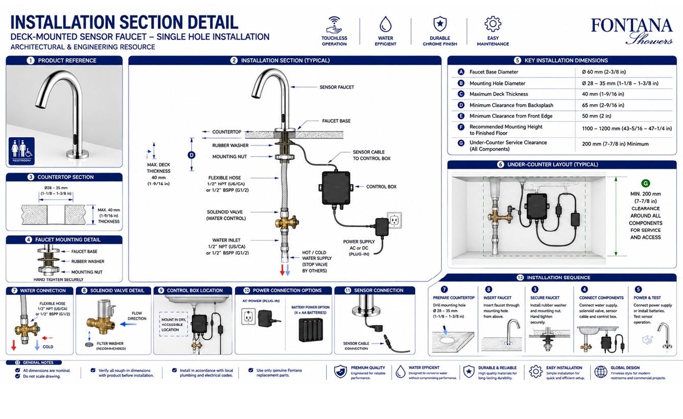
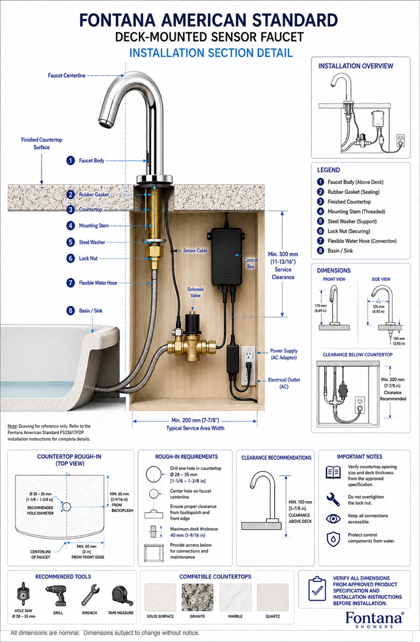
This installation section detail is intended to support architects,
plumbing engineers, electrical engineers, interior designers, contractors,
countertop fabricators, installers and facility managers coordinating the
Fontana American Standard deck-mounted automatic sensor faucet through the
finished countertop assembly. The technical drawing identifies the visible
faucet body, mounting base, finished-deck section, mounting stem, gasket,
washer, retaining hardware, flexible water connection, sensor cable,
solenoid valve, control box, power connection and required under-counter
service clearance.
Fontana American Standard Deck-Mounted Sensor Faucet
The Fontana American Standard Sensor Faucet is a single-hole,
deck-mounted automatic faucet designed for hands-free lavatory
operation. The installation section shows how the faucet body is
seated above the finished countertop and secured through the deck
using the model-specific mounting stem, sealing components,
retaining hardware and concealed connections.
The section drawing should be reviewed together with the approved
product specification and installation instructions. Final mounting
hardware, opening size, deck-thickness allowance, water connections,
control-component arrangement and power configuration must be
verified before installation begins.
-
Model:
FS2361TFDP
-
Installation:
Deck mounted
-
Mounting configuration:
Single hole
-
Finish:
Polished chrome
-
Material:
Brass
-
Faucet type:
Automatic motion-sensor sink faucet
-
Sensor:
Infrared touchless activation
-
Mounting opening:
Verify from the approved installation drawing
-
Deck-thickness allowance:
Verify from current product documentation
-
Water configuration:
Cold-water or optional hot-and-cold mixer configuration
-
Working pressure:
0.05–0.8 MPa
-
Power arrangement:
Verify the selected AC or battery configuration
-
Service requirement:
Maintain accessible under-counter components
Required Installation Section Drawing Package
Each section drawing should use a consistent scale, dimension style
and product-identification block. References should be taken from the
finished countertop surface, faucet centerline, mounting opening and
accessible under-counter service zone. The drawing should clearly
distinguish visible faucet components from the concealed mounting,
plumbing, sensor, control and power components located below the deck.
Installation Section Detail
Shows the complete faucet installation through the finished
countertop assembly. The section identifies the faucet body,
mounting base, countertop, mounting stem, sealing components,
retaining hardware, flexible connection, sensor cable and
under-counter operating components.
Faucet Body and Base
Identifies the visible faucet body and mounting base above the
finished countertop. The base should seat evenly on the deck,
remain centered over the mounting opening and maintain the
alignment established in the project drawings.
Finished Countertop Section
Shows the full countertop assembly through which the faucet is
installed. The section should include finish material,
substrate, reinforcement and any additional layers affecting
the mounting depth and hardware engagement.
Mounting Stem
Identifies the threaded or model-specific mounting stem passing
through the countertop opening. The stem should remain centered,
undamaged and sufficiently engaged with the securing hardware
below the deck.
Upper Sealing Gasket
Shows the sealing component positioned between the faucet base
and finished countertop. The gasket should be installed evenly
to support stable seating and help limit moisture entry around
the mounting opening.
Washer and Retaining Plate
Identifies the washer or retaining plate located below the
countertop. This component distributes the clamping load across
the underside of the deck and supports secure faucet mounting.
Lock Nut
Shows the securing nut installed on the mounting stem beneath
the deck. The lock nut should be tightened evenly according to
the approved installation instructions without overtightening
or damaging the countertop assembly.
Flexible Water Connection
Shows the flexible water line connecting the faucet assembly
with the solenoid valve, mixer or approved water-supply
arrangement. The hose should remain free from twisting, kinks,
compression and contact with sharp surfaces.
Solenoid Valve Connection
Identifies the accessible position and connection direction of
the solenoid valve controlling water delivery. The inlet and
outlet should follow the approved flow direction, with secure
and serviceable connections.
Sensor Cable Connection
Shows the electrical lead between the faucet sensor and
concealed control assembly. The cable should be routed away
from sharp edges, hot piping, standing water and moving cabinet
hardware.
Control Box Position
Identifies the under-counter control-box location serving the
faucet sensor and solenoid valve. The control box should remain
dry, protected, securely mounted and accessible for testing,
diagnostics and replacement.
Power Connection
Shows the connection to the approved battery pack, transformer
or model-specific electrical supply. Power components should be
located in a protected area and coordinated with the electrical
requirements of the selected configuration.
Optional Mixer Connection
Identifies the optional hot-and-cold mixing component when
specified. Hot and cold inlets and the mixed-water outlet should
be connected according to the approved installation instructions
and remain accessible for adjustment.
Under-Counter Clearance
Defines the clear area required for the mounting hardware,
flexible lines, mixer, solenoid valve, control box, power
components and sensor connections. Cabinetry and basin
components should not prevent installation or future servicing.
Engineering note:
Do not scale the installation section or establish mounting details
from estimated dimensions. Confirm the mounting opening, deck-thickness
allowance, stem engagement, hardware sequence, connection arrangement,
control-component position and power configuration using the current
FontanaShowers specification sheet, installation instructions and
approved project submittal before installation begins.
Installation Sequence Coordination
Prepare the Deck
Confirm the approved mounting-hole position, opening size,
finished-deck thickness and faucet centerline before drilling
or beginning installation.
Seat the Faucet
Place the approved sealing component and faucet base over the
mounting opening, keeping the fixture aligned with the basin
and project centerline.
Secure the Assembly
Install the lower washer, retaining plate and lock nut in the
required order. Tighten the hardware evenly while maintaining
the faucet’s position.
Connect the Water Supply
Connect the building supply, shutoff valve, optional mixer,
solenoid valve and faucet line according to the selected water
configuration.
Connect Sensor Components
Route and connect the sensor lead, solenoid cable and control
box connections without stretching, pinching or exposing the
cables to moisture.
Connect the Power Supply
Install and connect the approved battery pack, transformer or
model-specific power supply according to the electrical
configuration selected for the project.
Flush and Test
Flush the water supply as required, inspect all connections
for leakage and test sensor activation, water delivery and
automatic shutoff operation.
Confirm Service Access
Verify that the mounting hardware, shutoff valve, mixer,
solenoid, control box, power source and electrical connections
remain accessible after installation.
Architectural and MEP Coordination Considerations
Countertop Assembly
Coordinate the mounting assembly with the complete countertop
build-up, including finish material, substrate, reinforcement
and any supporting framework beneath the deck.
Basin Clearance
Confirm that the basin bowl, overflow, drain assembly and
backsplash do not conflict with the mounting stem, retaining
hardware or concealed connections.
Cabinet Coordination
Check drawers, shelves, cabinet framing and access panels to
maintain sufficient clearance around the faucet mounting and
operating components.
Water-Supply Access
Maintain access to the shutoff valve, supply connection,
optional mixer and solenoid valve for flushing, adjustment,
inspection and future replacement.
Electrical Access
Coordinate the power source, transformer, receptacle and cable
routing with the electrical drawings and locally adopted
electrical requirements.
Moisture Protection
Protect control and electrical components from active leaks,
standing water and routine cleaning spray while preserving
ventilation and maintenance access.
Installation Section and Technical Resources
American Standard Sensor Faucet Product Page
Product information, technical specifications, installation
documentation and available resources for the Fontana
deck-mounted automatic sensor faucet.
Deck-Mounted Sensor Faucet Installation Guide
Installation preparation, mounting, connection, testing,
commissioning and maintenance guidance for automatic sensor
faucets.
FontanaShowers Installation Hub
Central installation resources for automatic faucets,
soap dispensers and other FontanaShowers commercial fixtures.
Automatic Sensor Faucet Collection
Explore related deck-mounted, wall-mounted and commercial
automatic sensor faucet configurations and finish options.
Sensor Faucet BIM Files
BIM and architectural coordination resources supporting
sensor-faucet planning, documentation and multidisciplinary
project development.
Sensor Faucet Installation Resource
General setup information covering mounting, automatic
operation, concealed components, power supply, commissioning
and maintenance.
Professional Engineering and Accessibility References
Project verification:
Installation section drawings are coordination tools and do not replace
approved product specifications, installation instructions or project
submittals. The architect, plumbing engineer, electrical engineer,
countertop fabricator, contractor and licensed installer should verify
the final mounting opening, finished-deck thickness, hardware sequence,
stem engagement, gasket position, water connections, optional mixer,
solenoid valve, control-box location, power configuration, cable routing,
basin clearance, service access, accessibility criteria and locally
adopted codes before installation.
|
|
|