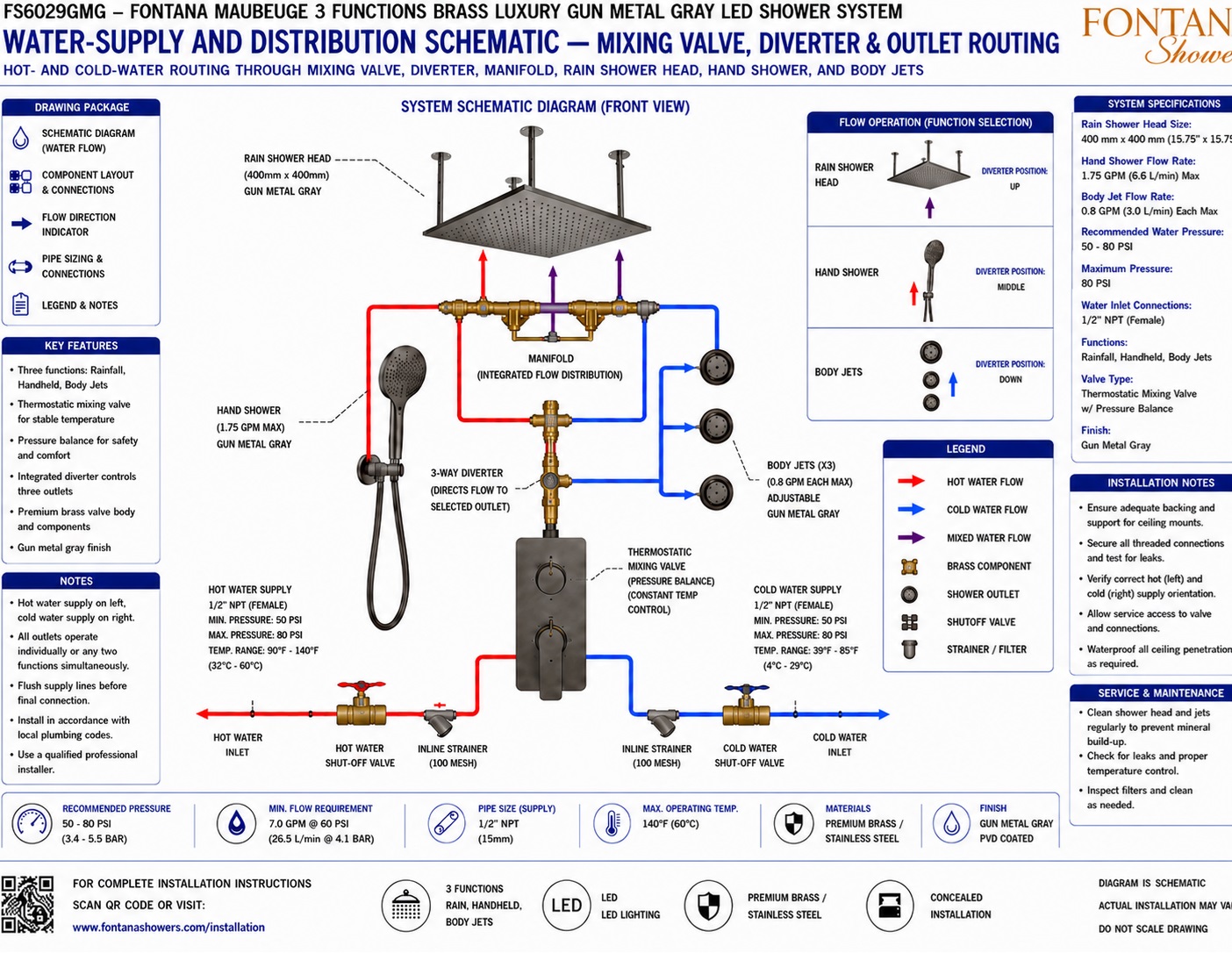
Diagram of Water Supply and Distribution
For Large Rain Shower Systems
A large rain shower system should be documented as one coordinated hydraulic assembly rather than a group of decorative fixture symbols. The schematic should clearly trace hot and cold water through the mixing valve, diverter, manifold, rain shower head, hand shower, and body jets.
Read More
A complete schematic identifies pipe routing, valve sequence, outlet zoning, connection sizes, isolation points, pressure relationships, and approved operating combinations. This gives architects, plumbing engineers, BIM coordinators, contractors, and commissioning teams a clear basis for reviewing total flow demand, temperature control, maintenance access, and component compatibility.
FontanaShowers multifunction systems may combine rainfall outlets, handheld showers, thermostatic controls, and body jets. Related BIM resources can support coordinated documentation of shower heads, mixers, valves, manifolds, and body sprays.
Routing Hot and Cold Water
Begin the schematic at the domestic hot- and cold-water branches. Identify the pipe size, design pressure, isolation valve, connection orientation, and direction of flow for each branch.
- Connect both supplies to the manufacturer-designated valve ports.
- Show service stops, strainers, check valves, and flushing provisions when included.
- Provide access for cartridge replacement, limit-stop adjustment, testing, and cleaning.
- Document an access strategy for every concealed valve.
Read More
A pressure-balancing or thermostatic mixing valve combines the two supplies and delivers tempered water to the selected outlet. Undocumented crossovers should be avoided, and concealed components should never be placed behind permanent finishes without a defined service-access plan.
Temperature regulation is both a safety and comfort requirement. Valve selection, capacity, certification, and field adjustment should be coordinated with approved product data, the adopted plumbing code, and the authority having jurisdiction.
Diverter Sequence and Mixing Valve
Downstream of the mixing valve, tempered water normally enters a diverter or multifunction selector. The schematic should state whether outlets operate one at a time or in approved simultaneous combinations.
Label Every Diverter Port
Use clear destination labels such as “rain shower head,” “hand shower,” and “body-jet manifold” instead of unexplained port numbers.
Define the Operating Sequence
Confirm during design whether rainfall, handheld, and body-jet functions operate independently or in selected combinations.
Assess Simultaneous Demand
Verify that the supply branch and valve can maintain adequate pressure and temperature when multiple outlets operate together.
Balance the Body-Jet Manifold
Use a coordinated manifold or hydraulically balanced arrangement so upper, middle, and lower jets deliver consistent performance.
Document Manifold Requirements
Show the location, inlet size, branch sizes, jet count, connection orientation, isolation provisions, and required access.
Coordinate With Hydraulic Calculations
Avoid generic tree-shaped piping when unequal branch lengths or pressure losses could produce inconsistent outlet performance.
Water-Distribution Coordination
Document each component, the drawing information it requires, and its role in AEC coordination.
Hot-Water Branch
Show pipe size, pressure, isolation valve, and flow direction to define the available heated-water supply.
Cold-Water Branch
Show pipe size, pressure, isolation valve, and flow direction to support pressure and temperature balance.
Mixing Valve: Identify the valve type, port orientation, limit-stop setting, and service access required to control tempered-water delivery.
Outlet and Distribution Coordination
Rain Shower Head
Document connection size, inlet location, design flow, and ceiling coordinates for the overhead outlet.
Hand Shower
Identify the wall outlet, hose connection, mounting location, and service requirements.
Body-Jet Manifold
Show the inlet size, branch arrangement, number of jets, and access needed for balanced distribution.
Isolation Valves
Locate valves in accessible service zones so individual components can be maintained without shutting down the complete system.
Rain Shower Head Connection
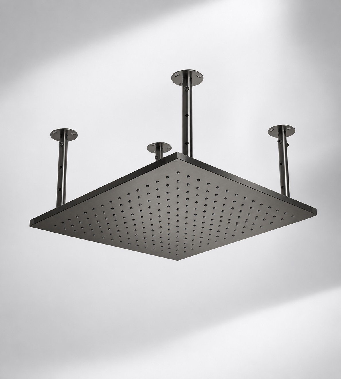
Use a direct, independently supported branch with minimal unnecessary fittings. Align the pipe center with the documented fixture inlet and reflected ceiling plan.
Read More
For ceiling-mounted rain heads, coordinate the piping schematic with the installation section, ceiling structure, finish depth, support method, and final threaded or flexible connection.
Hydraulic Performance Check
Verify branch size, residual pressure, valve capacity, elevation change, and pressure loss through the selected rain head.
Read More
Hydraulic demand is not determined by nominal fixture size alone. Multifunction heads with separate rainfall, waterfall, mist, or cascade inlets should have individually identified branches. Do not combine inlets unless the manufacturer expressly permits it.
Hand Shower Connection
Hand-Shower Branch Requirements
Coordinate the wall outlet, hose connection, holder or slide bar, backflow protection, mounting height, reach range, and accessibility requirements.
ASME A112.18.1/CSA B125.1
Confirm that shower heads, handheld showers, body sprays, diverters, hoses, and related fittings are listed, compatible, and correctly connected.
Sample AEC Coordination Project
An early hotel schematic undersized the diverter and omitted simultaneous-use criteria and a balanced body-jet manifold.
Technical Submittal Review
The plumbing engineer identified excessive combined demand, unequal branch lengths, and insufficient documented valve capacity.
Coordinated System Revision
The design was updated with a suitable thermostatic valve, labelled diverter ports, a balanced manifold, and accessible isolation points.
Commissioning Outcome
Early coordination reduced concealed-wall rework and established a clear test sequence for every outlet and approved operating mode.
Specification and Commissioning Standards
-
Final Submittal Requirements
should include valve flow data, pressure requirements, connection sizes, approved outlet combinations, manifold details, temperature-control certification, installation instructions, and access requirements.
-
Architect and Specifier Technical Resources
may include BIM files, CAD drawings, technical submittals, installation resources, and performance information for professional coordination.
-
FontanaShowers BIM File Hub
provides model and drawing resources for coordinated project documentation, including RVT, RFA, DWG, and IFC formats where available.
-
Commissioning Checklist
should verify hot- and cold-water orientation, flushing, leak-free connections, temperature-limit settings, diverter operation, body-jet balance, and performance in every approved mode.
-
Complete Distribution Schematic
translates a complex rain shower system into clear, coordinated, and buildable information.
A clearly mapped flow path from the hot- and cold-water branches through the mixing valve, diverter, manifold, rain shower head, hand shower, and body jets can reduce RFIs, support user safety, improve hydraulic performance, and simplify long-term maintenance.
|
|
|