Fontana Thermostatic Valve Installation
Coordinate the Thermostatic Valve Rough-In
Plan valve depth, supply orientation, outlet routing, structural support and access before closing the shower wall.
Installation Hub
Mixer
Wall Rough-In
Ceiling Outlet
Body Jets
Hand Shower
Frequently Asked Questions
How is thermostatic-valve rough-in depth established?
Measure from the finished wall plane and stay within the installation range specified for the exact valve and trim. Review Mixer Installation
Why must hot and cold supply orientation be verified?
Incorrect supply orientation can prevent proper temperature control. Follow the port markings and product-specific piping diagram.
What should be tested before closing the wall?
Flush the supplies, pressure-test concealed connections and verify valve and diverter operation according to the installation instructions.
Does the valve require future service access?
Maintain the access specified for cartridges, filters, stops and other serviceable components without obstructing the finished trim.
Large Rain Shower Head Systems
Thermostatic Valve Rough-In Detail
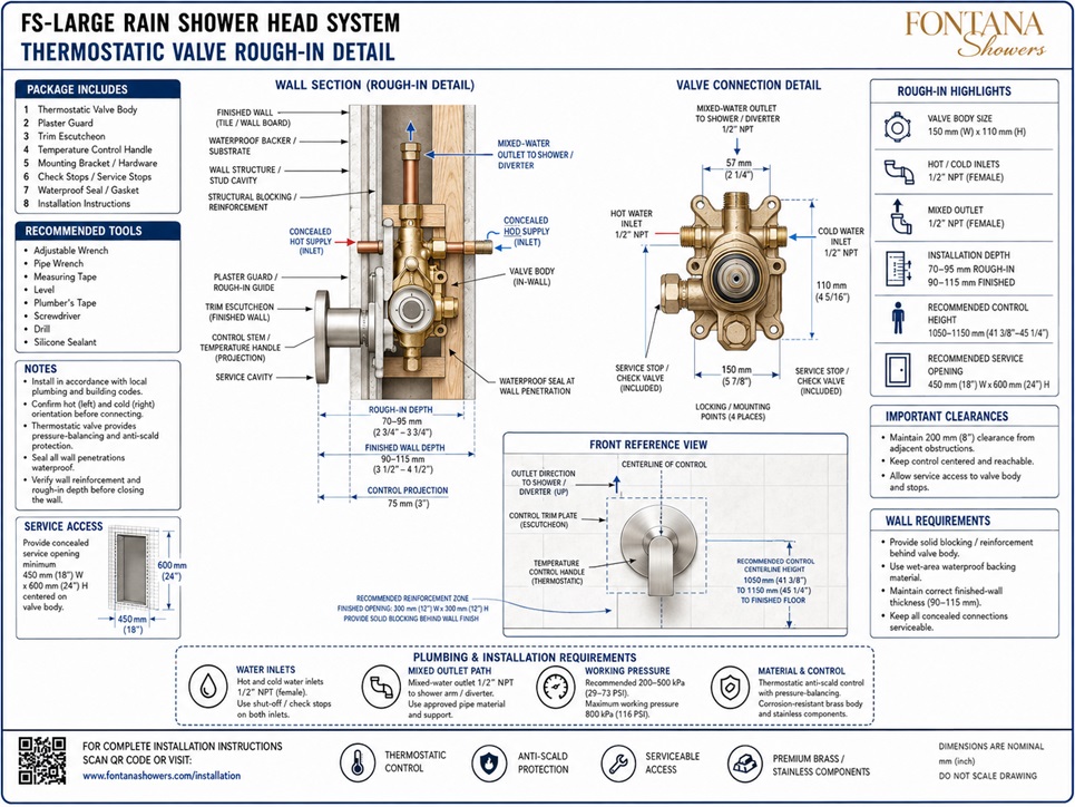
A thermostatic valve rough-in detail coordinates the concealed valve body with hot- and cold-water supplies, mixed-water outlets, finished-wall construction, trim controls and future service access. It gives architects, engineers, BIM coordinators, designers, contractors and commissioning teams a clear basis for accurate installation.
Read More
The construction detail should identify the valve position, rough-in depth, inlet orientation, outlet arrangement, structural support, waterproofing interface, temperature-control requirements and removable service zone. Final dimensions and connections should follow the approved product submittal rather than a generic valve symbol.
FontanaShowers provides concealed thermostatic mixers and multi-outlet configurations for rain shower heads, hand showers, body jets and other selectable functions, supported by BIM files, CAD drawings, dimensional information and installation resources.
Valve Body Position and Location
Show the concealed valve body by horizontal and vertical centerline, measured from permanent construction references and the final finished-wall plane.
- Identify the manufacturer-designated hot- and cold-water inlet ports.
- Use directional arrows to show flow through the mixing chamber and toward each outlet.
- Support the valve body independently with approved framing, blocking or a mounting plate.
- Support supply piping so installation forces are not transferred to the valve or wall finish.
- Coordinate the valve depth with the complete wall assembly and trim adjustment range.
Read More
- Document inlet size, connection type, pipe material, isolation valves, check valves, strainers and flushing provisions where required.
- Size the hot- and cold-water branches for available pressure, developed length, valve demand and simultaneous outlet use.
- Large rain heads used with body jets and a hand shower may require a different hydraulic design from a single-outlet shower.
- Confirm thermostatic performance and automatic compensating valve requirements with the approved product data, adopted code and ASSE 1016/ASME A112.1016/CSA B125.16.
Mixed-Water Outlet Coordination
Label every downstream connection by destination and document whether outlets operate independently or in approved combinations.
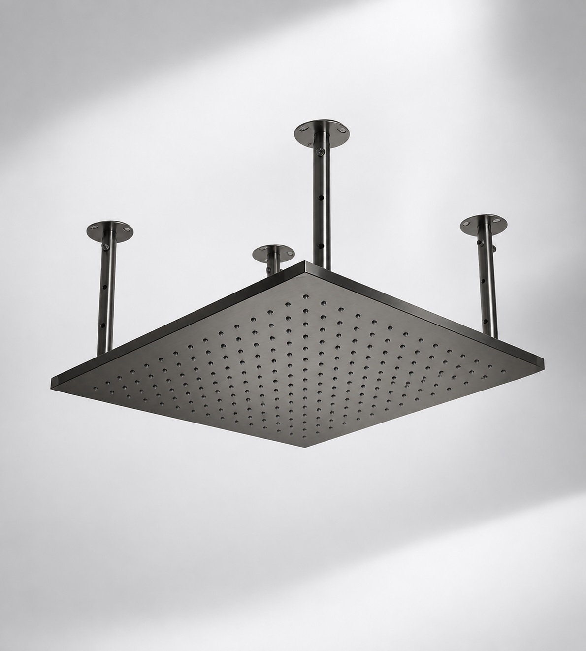
Rain Shower Head
Identify the mixed-water branch, connection size, inlet location and required operating flow.
Hand Shower & Auxiliary Outlets
Coordinate the hand shower, body-jet manifold, tub filler, waterfall, mist or massage function as applicable.
Operating Sequence
State whether the system permits one function at a time or approved simultaneous operation.
Read More
The operating sequence affects valve capacity, branch sizing, total flow demand and available residual pressure. BIM objects and shower-control families should be checked against the approved product submittal before rough-in dimensions are released for construction.
Finished-Wall Reference
Measure installation depth from the final wall face, not from framing, masonry or sheathing.
Read More
The complete wall build-up may include framing, backer board, waterproofing membrane, mortar, tile, stone or decorative panels. Every layer should be included when establishing the valve position.
Approved Rough-In Range
Show the manufacturer’s minimum and maximum depth and the installation reference mark relative to the finished surface.
Read More
Incorrect recess depth can prevent handles, sleeves, escutcheons or controls from seating correctly. Approved extensions should be documented as accessories, and the wall opening must remain within the trim plate coverage limits.
Coordination Schedule
Organize each component by required drawing information and its coordination objective.
Valve Body & Hot-Water Inlet
Show centerlines, orientation, support, port size, isolation and flow direction.
Cold-Water & Mixed-Water Connections
Document inlet orientation, connection size and the destination of every downstream outlet.
Depth & Temperature Control
Record the finished-wall reference, cartridge type, safety stop and commissioning procedure.
Service access: Document the wall opening, cartridge removal path, accessible shutoffs and tool clearances to support maintenance without demolition.
Temperature Control & Tuning
Valve and Control Schedule
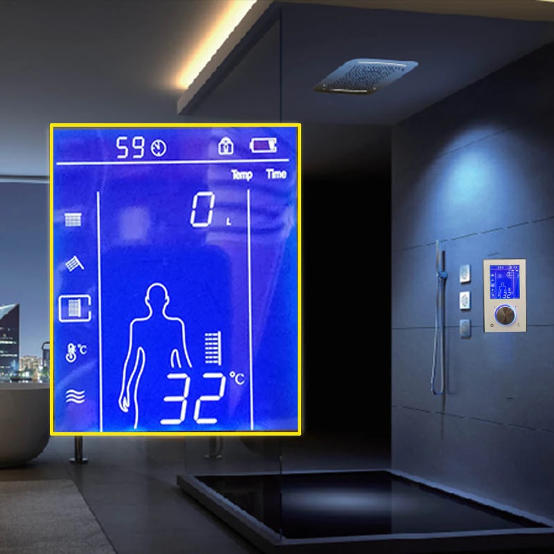
Specify the thermostatic cartridge, temperature-control handle, safety stop, maximum-temperature limit and commissioning requirements.
Field Temperature Verification
Test the final outlet temperature under operating conditions rather than relying only on handle markings.
Read More
Changes in incoming hot- or cold-water temperature may require the temperature-limit stop to be checked or readjusted. Documented commissioning and maintenance procedures are especially important in hospitality, multifamily, healthcare and other managed facilities.
Front Service Access
Where front servicing is permitted, cartridges, strainers, check valves, seals and service stops should remain accessible from the finished side.
Serviceable Valve Configuration
Select configurations designed for routine maintenance without removing concealed piping.
Cartridge Removal Clearance
Show the removal path, tool clearance, trim coverage and access to shutoffs or remote components.
Unobstructed Service Zone
Keep permanent stonework, mirrors, cabinetry and glass supports outside the required access area.
AEC Coordination Case Study
Complete Thermostatic Valve Documentation
A coordinated rough-in detail protects finished walls, improves hydraulic performance, reduces RFIs and supports safe long-term operation.
|
|
|