Fontana Touchless Systems™ Engineering
Faucet & Soap System
Engineering Installation
A multidisciplinary coordination framework for automatic faucets and touchless soap dispensers—from fixture layout and rough-in through controls, accessibility, commissioning and facility handover.
ArchitecturalFixture and basin layout
PlumbingWater, waste and soap
ElectricalPower and control routing
OperationsAccess and commissioning
Engineering Purpose One reference for every system interfaceA coordinated handwashing system crosses several scopes: fixture selection, countertop or wall conditions, basin geometry, water and waste, soap delivery, power, controls, accessibility and millwork. This page defines what the engineering package should communicate. Exact dimensions, connections and components must come from the approved documents for the selected Fontana product codes.
Responsibility Matrix Coordinate the drawing package by discipline
| Discipline | Primary coordination | Required verification |
|---|
| Architecture / Interiors | Fixture location, basin relationship, counter or wall construction and finish interfaces | Selected models, elevations, openings, reach and visible alignment |
| Plumbing | Water supply, shutoffs, filtration, mixing, valves, waste and soap delivery | Connection types, operating requirements, flushing and accessible service routing |
| Electrical | Specified power source, protected routing, transformers or control modules | Product power requirements, location, access and project electrical provisions |
| Accessibility | Reach, clear floor area, knee and toe space and protected below-counter elements | Complete installed condition under applicable project requirements |
| Millwork / Facilities | Equipment zones, access panels, reservoirs, tubing and replaceable components | No conflict with drawers, supports, waste piping or required clearances |
Required Drawing Package Views and information required for coordinationUse consistent product codes, equipment tags and references across every view.
Overall DimensionsPrincipal fixture geometry, projections, outlet relationships and mounting references.
Plan & ElevationsFaucet, dispenser, basin and surrounding construction shown together.
Countertop SectionOpenings, mounting surfaces, fixture hardware and below-counter equipment zones.
Plumbing SchematicWater path, shutoffs, filters, mixing, valve components, soap feed and waste.
Power & ControlsSpecified power arrangement, controllers, cable routing and protected connections.
Service AccessAccess panels and maintainable locations for valves, controls, filters and reservoirs.
Accessibility OverlayFixture operation and concealed equipment coordinated with required clearances.
Parts & ReferencesProduct codes, component tags, drawing references and model-specific documents.
Interface Checkpoints Resolve conflicts before fabricationThe engineering package should show the complete installed condition—not isolated product silhouettes.
Fixture + BasinStream landing, hand position, splash control and sensor relationship.
Fixture + CounterOpenings, thickness, support, spacing and mounting access.
Controls + MillworkClearance from drawers, framing, waste and fixed panels.
Services + AccessMaintainable water, power, soap and replaceable components.
Related Engineering Resources Continue into the detailed coordination setUse each supporting page for its defined project purpose.
Commissioning Record Verify operation and preserve the handover recordFollow the exact product procedures and record results for the facility team.
WaterFlushing, leakage, delivery and shutoff.
SoapFeed, dosing response and tubing condition.
SensorsActivation, separation and intended user zone.
DocumentsModels, settings, locations and service files.
Do not scale or universalize category-level informationUse approved product submittals and model-specific instructions for dimensions, connections, power, clearances and component locations. Project professionals must verify the complete installation against the selected products and applicable requirements.
Engineering Questions Coordination before installation
Which disciplines should coordinate the system?Architectural, interior, plumbing, electrical, accessibility and millwork requirements should be reviewed together using the exact approved faucet and dispenser models. What should an engineering submittal identify?Identify product codes, dimensions, mounting conditions, water and soap connections, power, controls, component locations, accessibility coordination and required service access. Why must basin geometry be shown?Spout reach, stream landing, sensor operation, dispenser position and splash control depend on the actual relationship between the fixtures, basin and countertop. What belongs in the commissioning record?Record flushing, leak inspection, power configuration, sensor response, faucet shutoff, soap operation, installed product codes and concealed component locations.
Touchless Installation Library
Return to the complete installation structure
Browse the touchless hub for installation guides or the master center for every FontanaShowers fixture category.
|
|
Fontana Touchless Systems Engineering
Coordinate the Touchless System Installation
Integrate fixture layout, plumbing, power, controls, accessibility, commissioning and maintenance access.
Installation Hub
Countertop
Plumbing
Accessibility
Sensor Faucets
BIM Files
Frequently Asked Questions
Which disciplines should coordinate a touchless handwashing system?
Architectural, plumbing, electrical, accessibility and millwork requirements should be coordinated using the exact approved products. Open BIM Resources
What should the engineering submittal identify?
Identify SKUs, dimensions, flow requirements, power, connections, control components, soap delivery and service clearances.
Why must basin geometry be reviewed?
Spout reach, water-stream location, sensor field and dispenser placement depend on the actual basin and counter relationship.
What belongs in the commissioning record?
Record flushing, leak tests, power configuration, sensor response, faucet shutoff, soap dosing and installed component locations.
Fontana Touchless Systems™ | Architectural and Engineering Resource
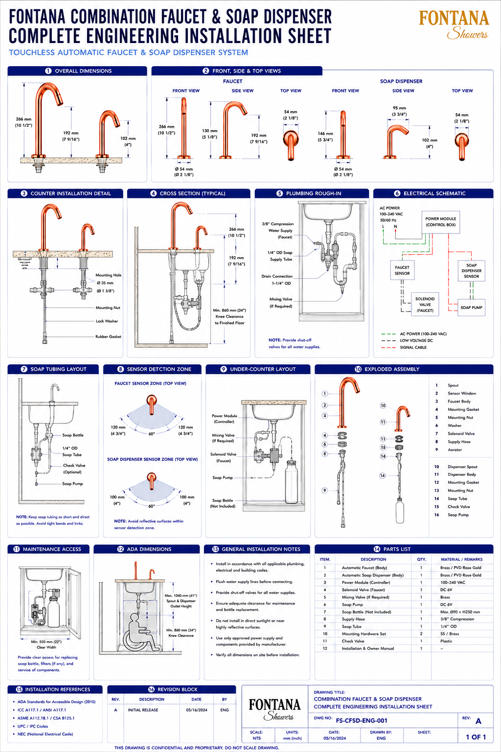
Fontana Combination Faucet & Soap Dispenser:
Complete Engineering Installation Sheet
This complete engineering installation resource is intended to support architects,
plumbing engineers, electrical engineers, MEP consultants, contractors, installers
and facility teams coordinating a Fontana automatic faucet and touchless soap
dispenser system. The sheet consolidates overall dimensions, front/side/top views,
countertop installation, cross section, plumbing rough-in, electrical schematic,
soap tubing, sensor zones, under-counter components, exploded assembly, maintenance
access, ADA dimensions, general notes, parts identification and drawing references.
Fontana Touchless Automatic Faucet & Soap Dispenser System
This coordinated fixture system combines a deck-mounted automatic faucet
and touchless soap dispenser with concealed plumbing, power, sensing and
soap-delivery components. The engineering sheet provides a single reference
for fixture geometry, mounting conditions, service requirements and
multidisciplinary installation coordination.
- Faucet overall height: 266 mm (10-1/2 in.)
- Faucet outlet height: 192 mm (7-9/16 in.)
- Soap-dispenser overall height: 146 mm (5-3/4 in.)
- Soap-dispenser outlet height: 102 mm (4 in.)
- Mounting-base diameter: Ø54 mm (2-1/8 in.)
- Mounting hole: Approximately Ø35 mm (1-3/8 in.)
- Faucet water supply: 3/8-inch compression
- Soap supply tube: 1/4-inch OD
- Drain connection: 1-1/4-inch OD
- Power input: 100–240 VAC, 50/60 Hz
- Minimum knee clearance: 860 mm (34 in.)
- Recommended service width: Approximately 550 mm (22 in.) minimum
Required Complete Engineering Installation Drawing Package
The engineering package should use consistent component numbering, dimensioning,
symbols and service references across all views. Drawings should coordinate
product geometry, countertop penetrations, plumbing and electrical connections,
sensor coverage, under-counter equipment locations, maintenance access,
accessibility requirements and replaceable components in one unified reference.
Overall Product Dimensions
Shows the principal faucet and soap-dispenser dimensions above the countertop, including overall heights, outlet heights and mounting-base proportions used for architectural and installation coordination.
Front, Side & Top Views
Provides orthographic views of both fixtures to clarify body geometry, outlet projection, base diameter and spatial relationships required for countertop layout and specification.
Counter Installation Detail
Illustrates the countertop penetrations, rubber gasket, lock washer, mounting nut and related hardware required to secure the faucet and dispenser bodies through the deck.
Cross Section
Shows the fixture bodies, countertop, sink, concealed mounting components and under-counter service area in section. The drawing also identifies the minimum knee-clearance relationship to finished floor.
Plumbing Rough-In
Coordinates the 3/8-inch faucet water supply, 1/4-inch OD soap tube, drain connection, optional mixing valve and required shut-off valves within the cabinet space.
Electrical Schematic
Shows 100–240 VAC input to the power/control module together with the faucet sensor, soap-dispenser sensor, faucet solenoid valve, soap pump and associated low-voltage signal wiring.
Soap Tubing Layout
Illustrates the soap reservoir, 1/4-inch OD tube, optional check valve and soap pump. Tubing should remain short, direct and free from sharp bends or kinks.
Sensor Detection Zones
Defines the faucet and soap-dispenser sensing fields in plan view and highlights the need to avoid reflective surfaces or obstructions that may interfere with reliable activation.
Under-Counter Layout
Shows the relative positions of the controller, optional mixing valve, faucet solenoid, soap pump and soap bottle to support compact installation while maintaining service access.
Exploded Assembly
Identifies major faucet and soap-dispenser parts including spouts, sensor window, bodies, gaskets, mounting hardware, hoses, tubing, aerator, check valve and pump components.
Maintenance Access
Establishes the minimum cabinet working width and clear service path needed to replace the soap bottle, inspect filters where provided and access serviceable plumbing and electrical components.
ADA Dimensions
Coordinates outlet height and minimum knee-clearance requirements for accessible installations. Final dimensions should be verified against current project-specific accessibility requirements.
General Installation Notes
Summarizes key field requirements including flushing supply lines, providing shut-off valves, maintaining maintenance clearances, avoiding highly reflective sensor conditions and verifying dimensions before installation.
Parts List & Revision Information
Provides a coordinated schedule of major system components together with drawing number, revision, units, issue date and sheet identification for project-document control.
Engineering note:
This complete engineering sheet is a coordination reference and should not be
scaled. Verify all dimensions, plumbing connections, power requirements,
sensor settings, mounting conditions, service clearances, ADA criteria and
component selections against current Fontana product specifications, approved
project submittals and manufacturer installation instructions before fabrication
or installation.
Architectural, Plumbing & Electrical Coordination Considerations
Countertop Preparation
Coordinate mounting-hole diameters, base locations, deck thickness and sink geometry before drilling or fabricating the countertop.
Water Supply
Provide compatible shut-off valves, mixing components where required and a properly flushed water supply before connecting the faucet system.
Electrical Power
Coordinate the power/control module, faucet sensor, dispenser sensor, solenoid valve and soap pump so wiring remains accessible and protected from moisture.
Sensor Performance
Keep sensor fields clear of reflective surfaces and nearby obstructions and verify both devices after installation for reliable touchless activation.
Under-Counter Service
Maintain sufficient cabinet access for the controller, valves, pump, soap bottle, drain and connection hardware without removing the countertop fixtures.
Accessibility
Coordinate knee clearance, outlet heights, approach space and exposed plumbing protection with the accessibility requirements applicable to the project.
FontanaShowers Installation and Specification Resources
FontanaShowers Product Catalog
Product information, finishes and technical documentation for Fontana touchless faucet and soap-dispenser systems.
Fixture Installation Resources
General installation information covering mounting, plumbing, electrical connections, testing, cleaning and maintenance.
Automatic Sensor Faucet Collection
Explore touchless faucet configurations, sensor technologies, control systems and commercial applications.
BIM and Design Resources
Architectural and engineering resources supporting fixture coordination, modeling and construction documentation.
Touchless Soap Dispenser Resources
Product information for automatic soap dispensers, pumps, reservoirs, tubing and control components.
Fontana Bathroom Faucet Collection
View related deck-mounted and commercial bathroom faucet designs for coordinated fixture selection.
Professional Engineering and Accessibility References
Project verification:
Complete engineering installation sheets are coordination tools and do not replace
approved construction documents or product submittals. The architect, plumbing
engineer, electrical engineer, contractor, accessibility consultant and qualified
installer should verify dimensions, mounting holes, plumbing and electrical
connections, sensor zones, service access, parts, accessibility requirements
and locally adopted codes before fabrication, installation and commissioning.
|
|
|